Image display device

a technology of image display and display screen, which is applied in the direction of projectors, color television details, instruments, etc., can solve the problems of reducing the utilization efficiency of light, difficulty in obtaining sufficient brightness, so as to reduce the effect of speckle noise and increase light utilization efficiency

Active Publication Date: 2015-05-07
JVC KENWOOD CORP A CORP OF JAPAN
View PDF6 Cites 17 Cited by
  • Summary
  • Abstract
  • Description
  • Claims
  • Application Information

AI Technical Summary

Benefits of technology

The technical effect of this patented technology is to improve the use of lasers by making them brighter without generating more noisy images.

Problems solved by technology

The technical problem addressed in this patent is the need for a small image display device that can be easily portable and used with a portable terminal owned by the user. The use of semiconductor light sources, such as LEDs or laser diodes, has advantages over traditional discharge lamps, but there are challenges associated with each. LEDs have low power consumption and are ideal for miniaturization, but they may not provide sufficient brightness when used as a light source. On the other hand, laser diodes offer higher brightness but may cause astigmatic difference in the spread of the beam, leading to lower utilization efficiency and potential speckle noise. The patent aims to address these challenges and provide a solution for a small image display device that can be easily portable and utilize semiconductor light sources efficiently without compromising image quality.

Method used


Image

  • Image display device
  • Image display device
  • Image display device

Examples


first embodiment

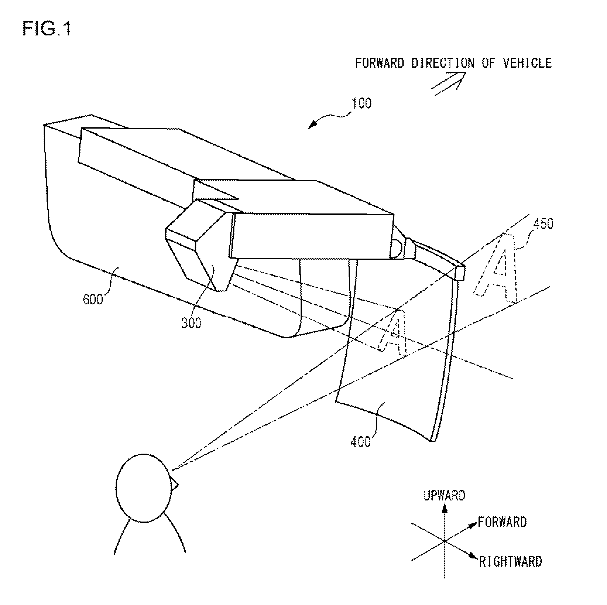
[0035]FIG. 1 shows an example of a head up display 100, which is an image display device according to a first embodiment. The head up display 100 is used while being attached to a rear-view mirror 600 of a vehicle. A combiner 400 of the head up display 100 reflects image display light projected from a projection unit 300 so as to allow a user to recognize the image display light as a virtual image and transmits a view outside the vehicle so as to allow the user to visually recognize the view. In FIG. 1, the projection unit 300 is projecting image display light related to an image of a letter “A” on the combiner 400. Looking at the combiner 400, the user recognizes the letter “A” in such a manner as if the letter were displayed, for example, 1.7 m to 2.0 m ahead (in a forward direction of the vehicle). In other words, the user can recognize a virtual image 450 of “A”. In the following, a central axis of the image display light projected on the combiner 400 from the projection unit 30...

second embodiment

[0063]FIG. 13 shows an optical system 800 arranged inside a projector, which is an image display device according to a second embodiment. As shown in this figure, laser light sources 1R, 1G, and 1B consisting of laser diodes emit red light, green light, and blue light, respectively. Beam expanders 2R, 2G, and 2B constituted of lenses change the red light, the green light, and the blue light, which are respectively incident, into collimated light.

[0064]A dichroic mirror 3R reflects the red light emitted from the beam expander 2R, bending the optical path thereof by 90 degrees. A dichroic mirror 3G reflects the green light emitted from the beam expander 2G, bending the optical path thereof by 90 degrees. The dichroic mirror 3G also combines the red light with the green light and emits resulting combined light. A dichroic mirror 3B reflects the blue light emitted from the beam expander 2B, bending the optical path thereof by 90 degrees. The dichroic mirror 3B also combines the combined...


PUM


Abstract

An image display device includes: a light source that emits a beam having a spreading angle in a first direction and a spreading angle in a second direction, which is smaller than the spreading angle in the first direction, in a direction perpendicular to the first direction; an afocal optical system member that has a focal point and changes the beam emitted by the light source into a parallel beam; an anisotropic diffusion plate that is arranged at the focal point and that widens at least the spreading angle in the second direction; a vibration unit that vibrates the anisotropic diffusion plate; a fly-eye lens array on which the parallel beam emitted from the afocal optical system member becomes incident; an image display element that modulates the beam that has passed through the fly-eye lens array into image display light.

Description


Claims


Application Information

Patent Timeline
Owner JVC KENWOOD CORP A CORP OF JAPAN
Why Eureka
Try Eureka