Mobile terminal and method of controlling the same

a mobile terminal and terminal technology, applied in the field of mobile terminals, can solve the problem of difficulty in executing a specific command for controlling only the application that is executed on the lower layer

Active Publication Date: 2015-05-07
LG ELECTRONICS INC
View PDF12 Cites 25 Cited by
  • Summary
  • Abstract
  • Description
  • Claims
  • Application Information

AI Technical Summary

Benefits of technology

[0009]Therefore, an object of the present invention is to provide a mobile terminal that is capable of controlling an application being executed on a lower layer of a display unit in an intuitive, easy manner, using a new type of user input unit provided on a rear-surface of the mobile terminal.

Problems solved by technology

Particularly, if the user desires to have access to the previously selected application and to input a predetermined control command while continuously maintaining the application that is currently being executed, he / she will have not only the inconvenience of having to perform many operations to switch between the applications, but also the difficulty in executing a specific command for controlling only the application that is executed on the lower layer.

Method used


Image

  • Mobile terminal and method of controlling the same
  • Mobile terminal and method of controlling the same
  • Mobile terminal and method of controlling the same

Examples


first embodiment

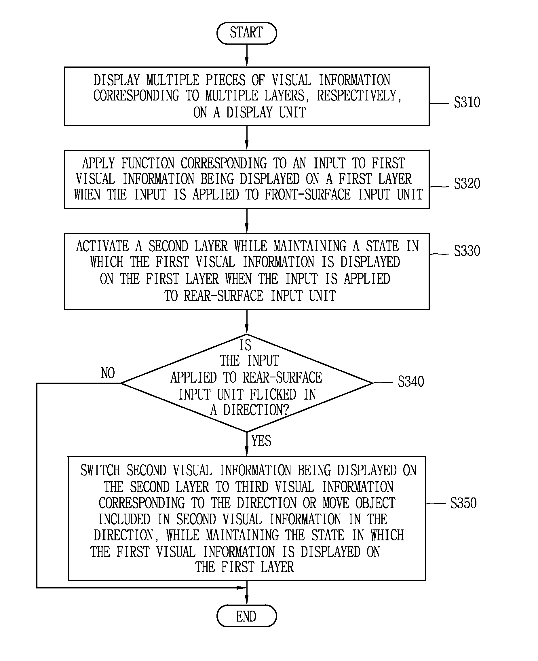
[0170] in a state where the visual information corresponding to each of the multiple layers is displayed on the display unit 151, the controller 180 detects the flicking touch input in the first direction that is applied to the front-surface input unit (that is, the touch screen) that is formed as a result of being integrated with the display unit 151. Then, while a moving image screen 710 being displayed on the uppermost layer is moved according to the flicking touch input in the first direction, when it is detected that the input is applied to the rear input unit 233, the controller 180 activates the lowermost layer of the display unit 151 and at the same time inactivates the uppermost layer. That is, the display change to the uppermost layer is not made, but, thereafter, the inputting of the control command into the uppermost layer is limited.

[0171]For example, in a state where the moving image screen 710 is output, in the form of a floating window, on the layer corresponding to ...

second embodiment

[0172] in a state where the visual information corresponding to each of the multiple layers is displayed on the display unit 151, the controller 180 detects the application of the input to the rear input unit 233. Then, in a state where the lowermost layer of the display unit 151 is activated according to the input into the rear input unit 233, if it is detected that the flicking input in the first direction is applied to the front-surface input unit (that is, the touch screen), the controller 180 executes the control command corresponding to the flicking touch input that is applied to at least a region of the first layer, which does not overlap the second layer. That is, the inputting of the control command into the uppermost layer is not limited.

[0173]On the other hand, if a touch event occurs on the rear input unit 233, the controller 180 displays a first icon corresponding to the touch event on one region of the display unit.

[0174]At this point, the first icon includes the visua...


PUM


Abstract

A mobile terminal including a display unit arranged on the front surface so multiple pieces of visual information corresponding to multiple layers, respectively; and a front-surface input unit so a control command is input into the front-surface input unit and a rear input unit arranged on the rear surface so the control command is input into the rear input unit; and a controller to apply a function corresponding to an input to first visual information displayed on a first layer, and activate a second layer arranged under the first layer while maintaining a state in which the first visual information is displayed on the first layer in response to input to the rear input unit.

Description

CROSS REFERENCE TO RELATED APPLICATIONS[0001]Pursuant to 35 U.S.C. §119A, this application claims the benefit of earlier filing date and right of priority to Korean Application No. 10-2013-0133689 filed on Nov. 5, 2013 the contents of which is incorporated by reference herein in its entirety.TECHNICAL FIELD[0002]The present invention relates to a mobile terminal equipped with a user input unit into which a control command is input.BACKGROUND ART[0003]A mobile terminal is a device that can be carried around and has one or more functions such as to perform voice and video call communications, inputting and outputting information, storing data, and the like.[0004]As functions of the terminal become more diversified, the terminal can support more complicated functions such as writing memos, receiving and transmitting e-mails and managing schedules. By comprehensively and collectively implementing such functions, the mobile terminal may be embodied in the form of a multimedia player or a...

Claims


Application Information

Patent Timeline
Patent Type & Authority Applications(United States)
IPC IPC(8): G06F3/0484G06F1/16G06F3/041G06F3/0481G06F3/0488
CPCG06F3/0484G06F3/0481G06F2203/04104G06F3/041G06F1/1692G06F3/0488G06F2203/04808G06F3/048H04B1/40
Inventor OH, YOUNJUCHUNG, JUNGMUNHONG, JIHOON
Owner LG ELECTRONICS INC
Why Eureka
Try Eureka