
Motor control device
a technology of motor control and control device, which is applied in the direction of motor/generator/converter stopper, electronic commutator, dynamo-electric converter control, etc., can solve the problems of difficulty in expanding the output voltage range or the output current range of the motor, and achieve the effect of expanding the output voltage range or the output current range of the motor, and expanding the output range of the available outpu
- Summary
- Abstract
- Description
- Claims
- Application Information
AI Technical Summary
Benefits of technology
Problems solved by technology
Method used
Image

Examples
first embodiment
[0025]A description will be given of the motor control device 1 according to the first embodiment of the present invention with reference to FIG. 1 to FIG. 7.
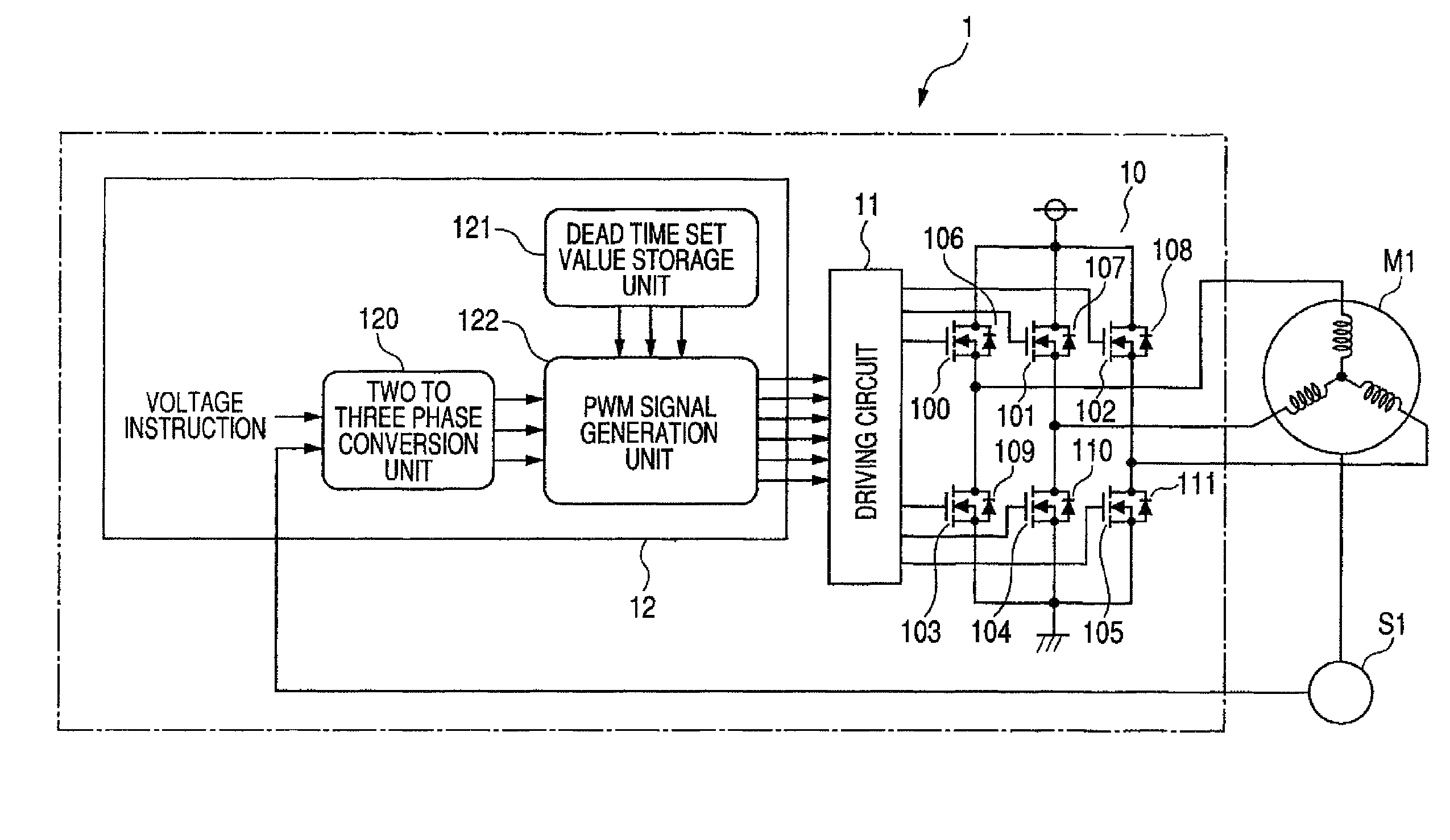
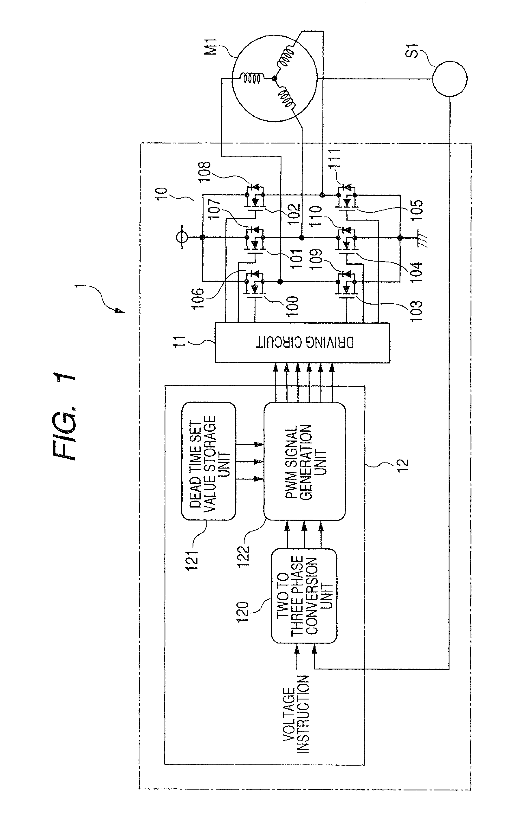
[0026]FIG. 1 is a block diagram showing the motor control device 1 according to the first embodiment.
[0027]The motor control device 1 shown in FIG. 1 is a device to control a three phase AC motor M1. The motor control device 1 controls a phase voltage to be supplied to the three phase AC motor M1. The three phase AC motor M1 is equipped with a rotation angle sensor S1.
[0028]The three phase AC motor M1 is composed mainly of the three phase bridge circuit 10 (as a multi-phase bridge circuit), a driving circuit 11, and a microcomputer 12 (as a control means).
[0029]The three phase bridge circuit 10 is composed of six MOSFETs 100 to 105 (as three pairs of switching elements). The microcomputer 12 instructs the driving circuit 11 to turn the MOSFETs 100 to 105 on and off.
[0030]As shown in FIG. 1, each of fly wheel diodes 106 to 111 i...
second embodiment
[0082]A description will be given of the motor control device according to the second embodiment of the present invention with reference to FIG. 9.
[0083]FIG. 9 is a block diagram showing the circuit structure of the motor control device 2 according to the second embodiment of the present invention. As shown in FIG. 9, the motor control device 2 is equipped with a microcomputer 22 (as a control means), a driving circuit 21, and a three phase bridge circuit 20 (as the multi-phase bridge circuit). The motor control device 2 controls the operation of a three phase AC motor M2 equipped with a rotation angle sensor S2. The microcomputer 22 is composed mainly of a three-phase conversion unit 290, a dead time set value storage unit 223, a PWM signal generation unit 224, an offset compensation value storage unit 221, and a dead time set value storage unit 223.
[0084]The three phase AC motor M2, the rotation angle sensor S2, the three phase bridge circuit 20, and the driving circuit 21 in the ...
third embodiment
[0094]A description will be given of the motor control device according to the third embodiment of the present invention with reference to FIG. 10.
[0095]FIG. 10 is a block diagram showing the circuit structure of the motor control device 3 according to the third embodiment of the present invention. As shown in FIG. 10, the motor control device 3 according to the third embodiment is equipped with a microcomputer 32 (as a control means), a driving circuit 31, and a three phase bridge circuit 30 (as the multi-phase bridge circuit). The motor control device 3 controls the operation of a three phase AC motor M3 equipped with a rotation angle sensor S3.
[0096]The three phase AC motor M3, the rotation angle sensor S3, the three phase bridge circuit 30, and the driving circuit 31 in the third embodiment shown in FIG. 10 are the same in structure, function and operation of the three phase AC motor M1, the rotation angle sensor S1, the three phase bridge circuit 10, and the driving circuit 11 ...
PUM
 Abstract
Description
Claims
Application Information