Device for digging diaphragms

a diaphragm and bucket technology, applied in the field of clamshell bucket digging devices, can solve the problems of reducing the storage capacity of diaphragms, so as to achieve the lowest possible cost, facilitate the operation of excavation, and reduce the cost

Active Publication Date: 2015-05-14
SOILMEC
View PDF4 Cites 13 Cited by
  • Summary
  • Abstract
  • Description
  • Claims
  • Application Information

AI Technical Summary

Benefits of technology

[0016]The aim of the present invention is therefore to provide a device for digging diaphragms, of the clamshell bucket type, which is able to overcome the aforementioned drawbacks of the prior art in an extremely simple, cost-effective and particularly functional manner.
[0017]In detail, an object of the present invention is to provide a device for digging with a bucket that, for the same digging section, has a storage capacity of the soil dug that is tangibly greater than that of a conventional bucket. This object according to the present invention is achieved by providing a device for digging with a bucket that maintains the simplicity of construction and of use of current buckets, also limiting the motorisations required for additional actuations.
[0018]The device for digging with a bucket according to the present invention, while being more efficient with respect to analogous known devices, is particularly simple and aimed at the lowest possible cost. Such a device, proposed in two different embodiments, requires a lengthening of the time to carry out the aforementioned steps 3 and 6, but offers a substantially greater storage capacity with respect to that of a conventional bucket. By analysing the duration of the operating cycles as a function of depth, the device for digging with a bucket according to the present invention also offers the possibility of using the bucket in the conventional way in the first tens of metres of the excavation, in other words not exploiting the increased load capacity, so as not to lengthen the times of steps 3 and 6, and instead exploiting the cumulative capacity only when the duration of the descent and ascent steps is substantial.

Problems solved by technology

Milling cutters are more mechanically complex and more expensive with respect to buckets because they are equipped with cutting wheels and hydraulic pumps for sucking up debris and their use requires more hydraulic power.
Buckets require less power than milling cutters, but they have the drawback of reaming the walls of the hole made during every transit step both going down and coming up (the excavation is of the discontinuous type).
They have a relatively limited storage capacity during each individual operating cycle.
In hard ground, moreover, the forward movement of a bucket is extremely limited and must be aided with the help of bits and grapnels.
Finally, it is clear that a bucket becomes less effective as the depth of the excavation increases, since it also increases the time taken to obtain an ever increasing volume of material extracted.
During ascent and descent, in addition to winding up and unwinding the support cable, it is also necessary to wind up and unwind all of the hydraulic tubes and electrical cables that drive the actuators of the bucket and this involves mechanical complications, greater wear, greater exposure to damage and additional costs.
Therefore, it is not suitable to excessively increase the speed of ascent of the bucket, since it would promote a sucking effect that could compromise the stability of the walls of the excavation.
Indeed, in practice, the volume of the extracted material is only a fraction of the theoretical volume since the flow of stabilizing liquid, which passes through the framework of the apparatus, which is not really hydrodynamic, disperses a great deal of the dug material, which falls to the bottom of the excavation.
Such an apparatus also has the drawback of taking longer to be filled, particularly in the presence of cohesive soil.
Moreover, it is necessary to make the hydraulic plant more complicated and to have high power to supply the motors of the helixes.

Method used


Image

  • Device for digging diaphragms
  • Device for digging diaphragms
  • Device for digging diaphragms

Examples


first embodiment

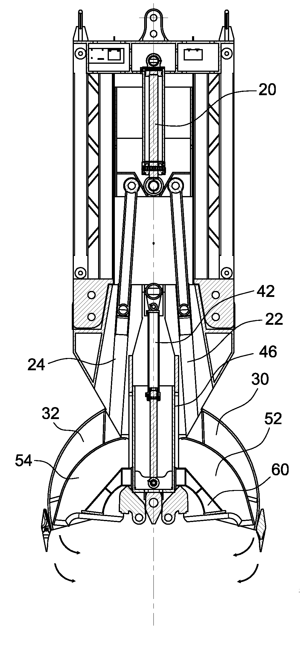
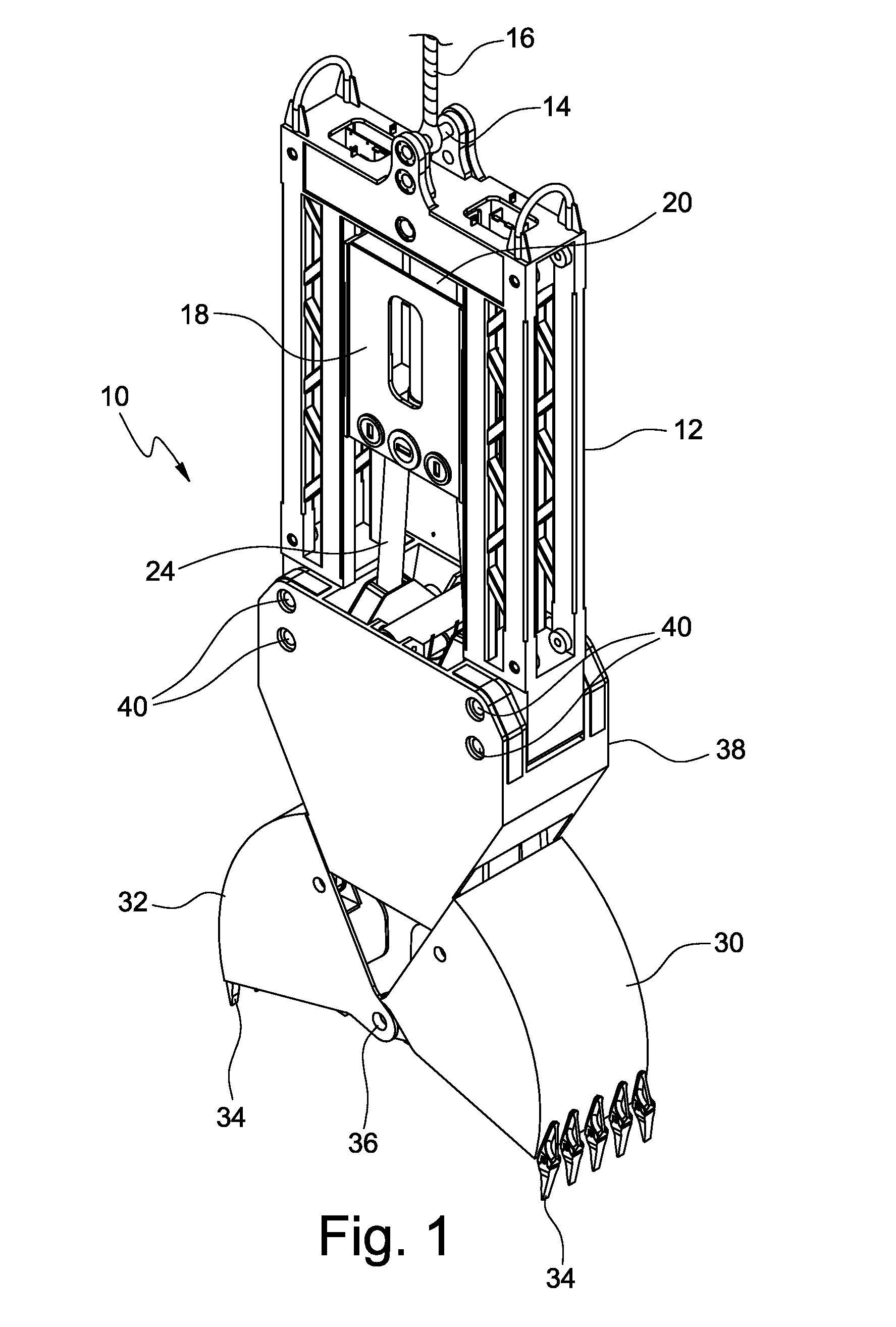
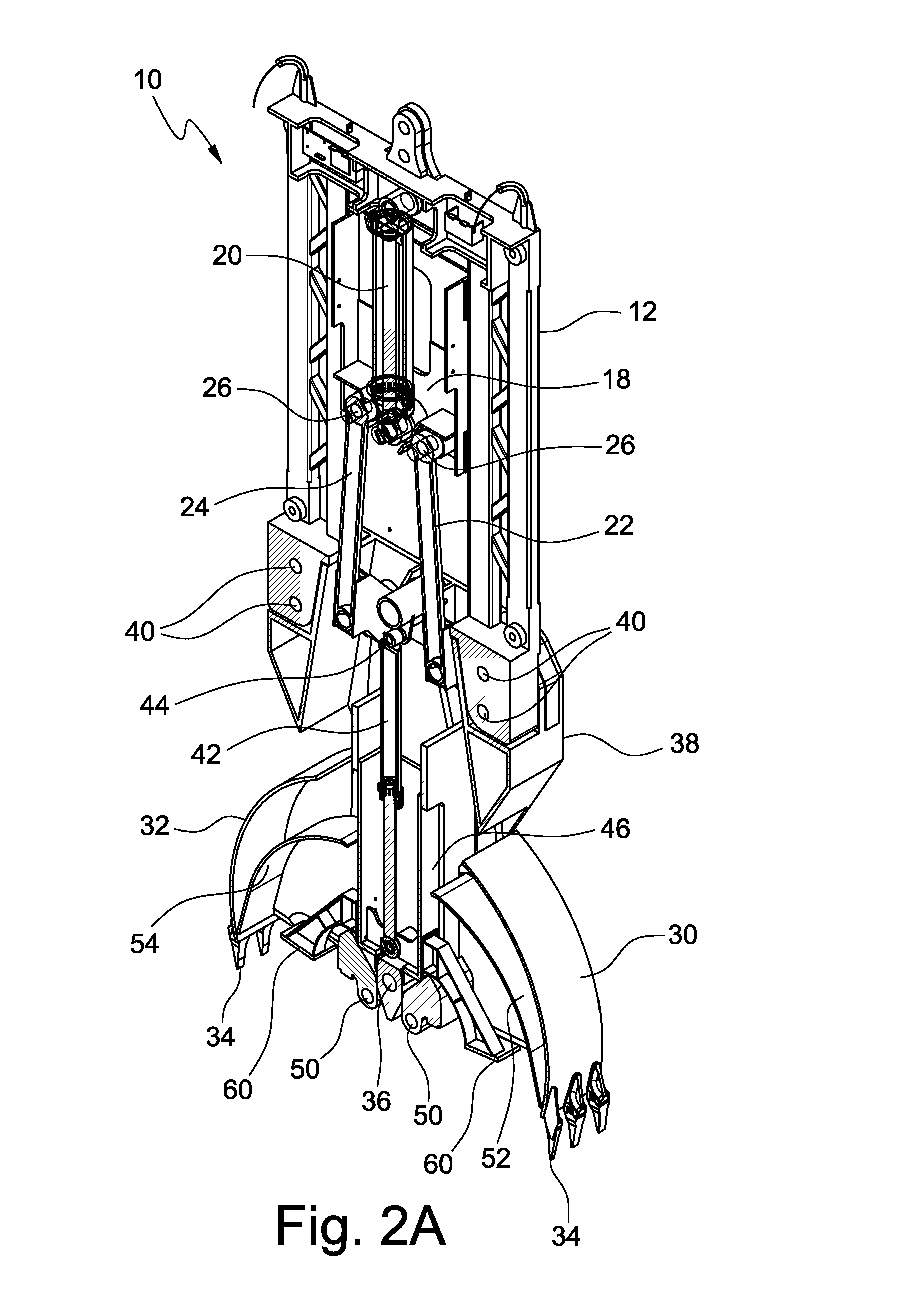
[0030]In the device 10 shown in FIGS. 1, 2A, 2B and 3A-3J the digging half-shells 30 and 32 are defined as “outer” half-shells. The outer half-shells 30 and 32 preferably but not necessarily have a common rotation axis 36 made on a half-shell support body 38 able to be temporarily fixed in a static manner, with removable means such as for example screws or pins 40, in the lower part of the framework 12. The half-shell support body 38 thus extends below said a framework 12 until it reaches a lower position that is close to the same depth reached by the digging teeth 34 when the outer half-shells 30 and 32 are in open position.

[0031]A second hydraulic cylinder 42, preferably fixed in its static part on the half-shell support body 38 through a pin 44, moves a second sliding trolley 46 (FIGS. 2A and 2B) guided on the structure of said a half-shell support body 38. The cylinder 42 could be connected at the top to the framework 12. The second sliding trolley 46 is provided, in its lower p...

second embodiment

[0049]In the device 10 shown in FIGS. 4, 5 and 6A-6H the digging half-shells 130 and 132 necessarily have distinct rotation axes, made on the half-shell support body 138 and represented by the respective pins 136A and 136B. The half-shell support body 138 is again fixed in a static manner, with screws or pins 140, in the lower part of the framework 12. The half-shell support body 138 thus extends beneath such a framework 12.

[0050]The second hydraulic cylinder 142, fixed in its static part on the half-shell support body 138 through a pin 144, moves the second sliding trolley 146 guided on the structure of said a half-shell support body 138. The second sliding trolley 146 is provided, on its side walls, with two attachment protuberances 162 on which, through upper pins 164, two further connecting rods 166 are hinged. Two mechanisms 168 and 170 with compass structure with the arms open at a slightly acute angle, otherwise known as “bolts”, are hinged on the pins 136A and 136B about whi...


PUM


Abstract

Disclosed a device for digging diaphragms, including a framework and a half-shell support body, fixed in the lower part of the framework, which supports a first pair of half-shells moved to open and close by a first actuation system. The device also has a reservoir operatively connected to the first pair of half-shells to contain the soil dug by half-shells. The reservoir is normally positioned between the framework and the half-shells and has a volume configured to contain an amount of soil corresponding to the amount of soil dug by such half-shells during a single operating cycle of the device. The device can also include separation means actuated for isolating the soil contained in the reservoir.

Description

CROSS-REFERENCE TO RELATED APPLICATIONS[0001]The present application claims the priority of Italian Patent Application No. MI2013A001529, filed Sep. 17, 2013, the contents of which are incorporated herein by reference.FIELD OF THE INVENTION[0002]The present invention refers to a digging device of the clamshell bucket type, usable in the field of foundations and, more specifically, for making structural or water-proofing diaphragms.BACKGROUND OF THE INVENTION[0003]By structural diaphragm we mean, in short, a trench of great depth configured to isolate a certain portion of soil. The trench, which can have a variable thickness of between a few tens of centimetres and a few metres, can be even hundreds of metres long. Such a trench is made by digging a plurality of rectangular sectors in sequence. Each of these rectangular sectors is filled with cement mixture and, if necessary, can be reinforced with a steel cage or with IPE beams.[0004]The equipment mainly configured for digging the r...

Claims


Application Information

Patent Timeline
Patent Type & Authority Applications(United States)
IPC IPC(8): E02F3/47
CPCE02F3/475E02D17/13E02F3/144
Inventor TREVISANI, STEFANOBISERNA, EZIOCURIC, JASMINPEDRELLI, MARCO
Owner SOILMEC
Why Eureka
Try Eureka