Cooling device for a rolling mill work roll

a technology of cooling device and work roll, which is applied in the direction of metal rolling arrangement, metal-working apparatus, manufacturing tools, etc., can solve the problems of reducing cooling efficiency, affecting the cooling affecting the efficiency of work rolls, so as to increase the cooling efficiency of liquid coolants.

Active Publication Date: 2015-05-14
PRIMETALS TECH USA
View PDF8 Cites 4 Cited by
  • Summary
  • Abstract
  • Description
  • Claims
  • Application Information

AI Technical Summary

Benefits of technology

[0005]Broadly stated, embodiments of the present invention are directed to disrupting the Leidenfrost effect, thereby increasing the cooling efficiency of a liquid coolant being applied to a work roll surface.

Problems solved by technology

Although such devices operate in a generally satisfactory manner, it has now been determined that their efficiency is compromised by the Leidenfrost effect, a phenomenon in which a liquid, in near contact with a body significantly hotter than the liquid's boiling point, produces an insulating vapor layer that keeps the liquid from boiling rapidly.
The thermal conductivity of the vapor is much poorer than that of the liquid, resulting in reduced cooling efficiency.

Method used


Image

  • Cooling device for a rolling mill work roll
  • Cooling device for a rolling mill work roll
  • Cooling device for a rolling mill work roll

Examples


Embodiment Construction

[0017]The components described hereinafter as making up the various embodiments are intended to be illustrative and not restrictive. Other suitable components that are capable of performing the same or similar functions as well as the materials described herein are intended to be encompassed within the scope of the present invention.

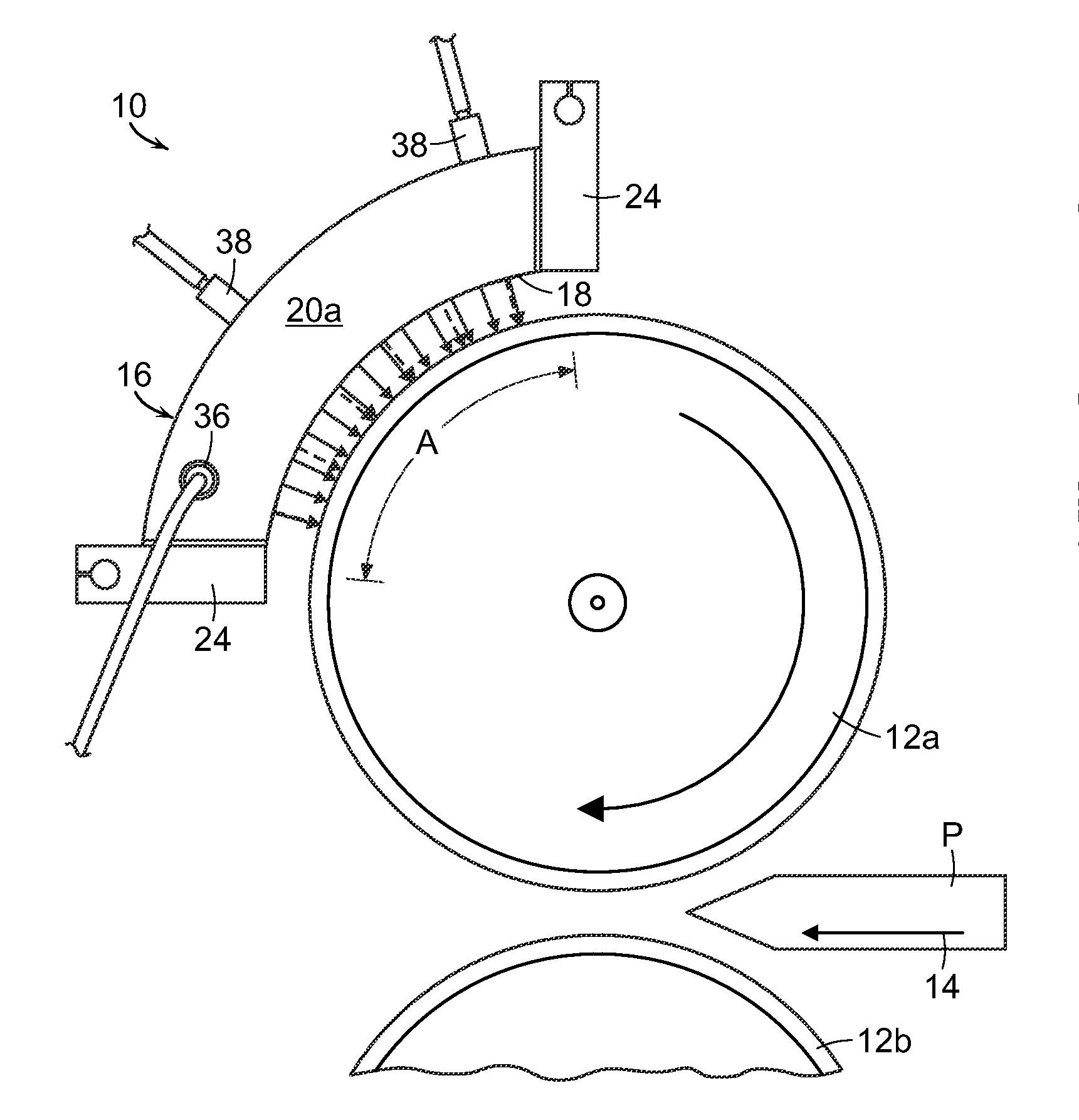
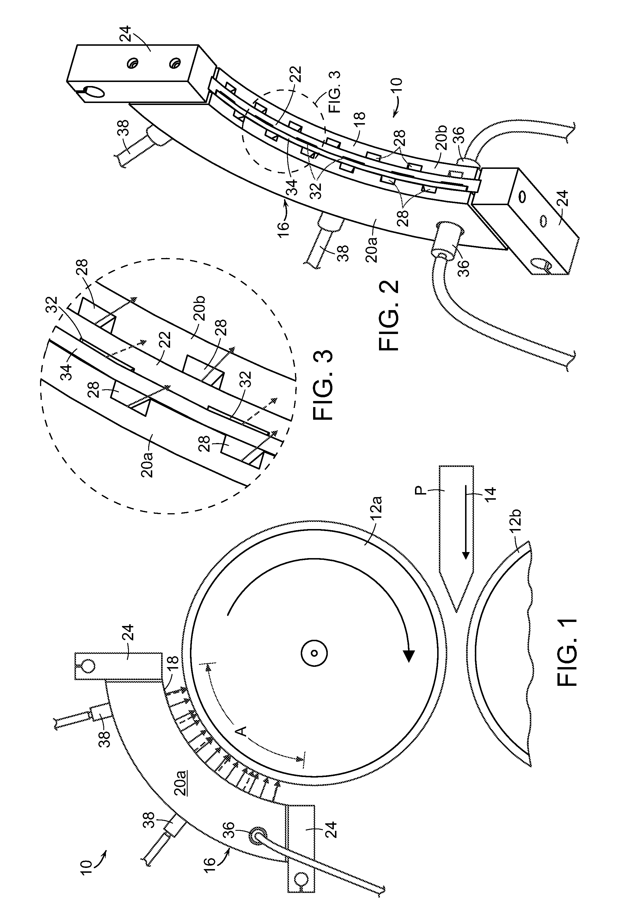
[0018]With reference initially to FIG. 1, a cooling device in accordance with an exemplary embodiment of the present invention is generally depicted at 10 at a location adjacent to a work roll 12a. Work roll 12a and a companion work roll 12b define a roll pass therebetween configured and dimensioned to roll a product “P” moving in the direction diagrammatically indicated by arrow 14.

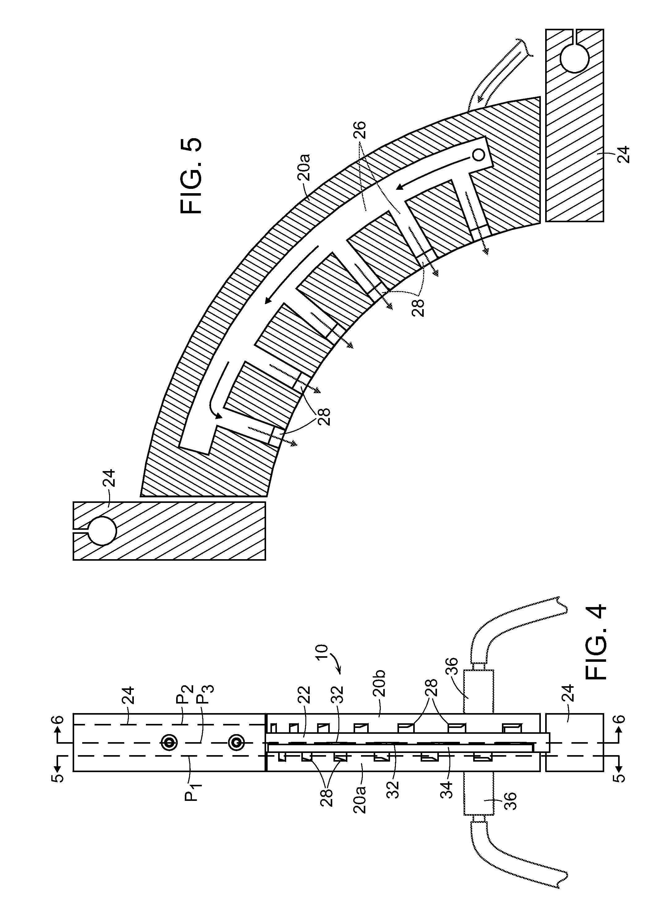
[0019]The cooling device 10 comprises a manifold housing 16 having a generally concave inner edge 18 configured and dimensioned to surround a surface area “A” of the work roll 12a.

[0020]With reference additionally to FIGS. 2-7, it will be seen that the manifold housing 16 ma...


PUM

PropertyMeasurementUnit
surface areaaaaaaaaaaa
boiling pointaaaaaaaaaa
thermal conductivityaaaaaaaaaa

Abstract

A cooling device comprises a manifold housing having a generally concave inner edge configured and dimensioned to surround a surface area of a work roll in a rolling mill. The manifold housing is of a modular design having multiple constituent sections that are internally configured to simultaneously apply both a liquid coolant and a pressurized gas to the surface area of the work roll.

Description

BACKGROUND[0001]1. Field[0002]Embodiments of the present invention relate generally to the cooling of work rolls in a rolling mill, and are concerned in particular with improving the cooling efficiency of liquid coolants such as water or the like applied to the roll surfaces.[0003]2. Description of Related Art[0004]In a known arrangement, as disclosed for example in U.S. Pat. No. 6,385,989 (Cassidy), a coolant delivery device partially surrounds a work roll and serves as a supply manifold for nozzles arranged to apply cooling water to the roll surface. Although such devices operate in a generally satisfactory manner, it has now been determined that their efficiency is compromised by the Leidenfrost effect, a phenomenon in which a liquid, in near contact with a body significantly hotter than the liquid's boiling point, produces an insulating vapor layer that keeps the liquid from boiling rapidly. The thermal conductivity of the vapor is much poorer than that of the liquid, resulting ...

Claims


Application Information

Patent Timeline
Patent Type & Authority Applications(United States)
IPC IPC(8): B21B27/10
CPCB21B2027/103B21B27/10
Inventor DAUPHINAIS, RAYMOND P.
Owner PRIMETALS TECH USA
Why Eureka
Try Eureka