Single-cup extraction system based on puncture by mechanical external force
An external force, single-cup technology, applied in beverage preparation devices, household appliances, applications, etc., can solve the problem of low liquid outlet efficiency
- Summary
- Abstract
- Description
- Claims
- Application Information
AI Technical Summary
Problems solved by technology
Method used
Image
Examples
Embodiment 1
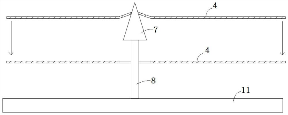
[0037] Embodiment 1, as Figure 3a As shown, the needle 6 includes a head 7 and a body 8, the section width of the head 7 is larger than the section width of the body 8, the preferred technical solution is that the head 7 is in the shape of a cone, and the body 8 is in the shape of a column . The head 7 of the needle 6 punctures the pressure-bearing layer 4. Since the head 7 is small at the top and large at the bottom, the head 7 will temporarily block the holes in the pressure-bearing layer 4 until after the water is injected, the water first dissolves the powder, and the pressure-bearing layer 4 is subjected to pressure. The pressure moves downward, and after the pressure is too large, the pressure-bearing layer 4 moves downwards and breaks away from the head 7 of the needle 6, and comes to the body 8. The cross-sectional width of the body 8 is smaller than the cross-section width of the head 7, so that the pressure-bearing layer 4 and the Holes between the puncture needles...
Embodiment 2
[0038] Embodiment 2, the drainage cavity 5 is provided with a filter layer 10, the filter layer 10 is provided with puncture holes 26 matched with the puncture needles 6, and the aperture of the filter layer 10 is smaller than the size of the drink powder particles. The traditional needles 6 are mostly columns or cones with sharp tops. When the needles 6 pierce the pressure-bearing layer, when the needles 6 pass through the needle holes 26, the lower parts of the needles 6 will block the needle holes 26. , thereby preventing the insoluble or undissolved powder from flowing out from the needle hole 26, ensuring the effectiveness of the filter layer and solving the above problems.
Embodiment 3
[0039] Embodiment 3, as Figure 3b As shown, in combination with Embodiment 1 and Embodiment 2, the bottom of the needle 6 in Embodiment 1 is provided with an abutment 9 with a cross-sectional width larger than the needle hole 26, and the abutment 9 is a columnar body or a cone, so that the needle 6 passes through the The abutment 9 located at the bottom of the puncture needle 6 behind the puncture needle hole 26 blocks the puncture needle hole 26, realizes the blocking of the puncture needle hole 26, ensures the liquid outlet efficiency, and also solves the problem of powder falling.
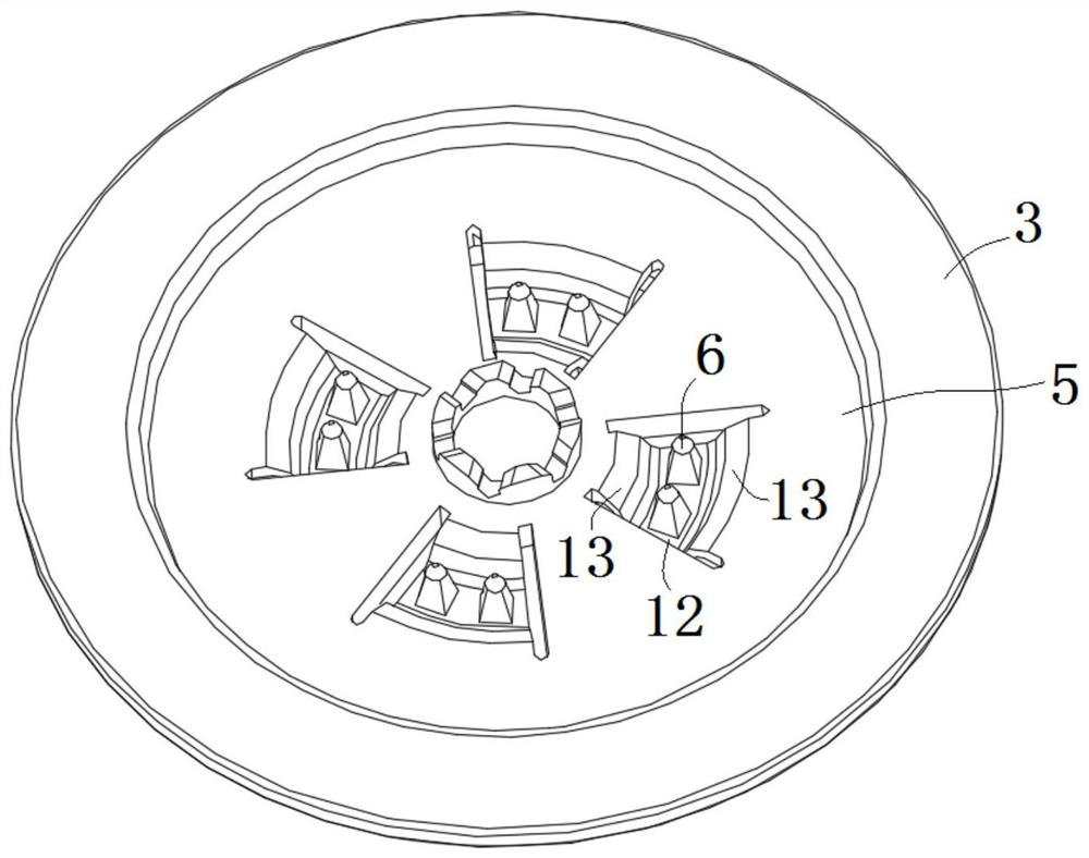
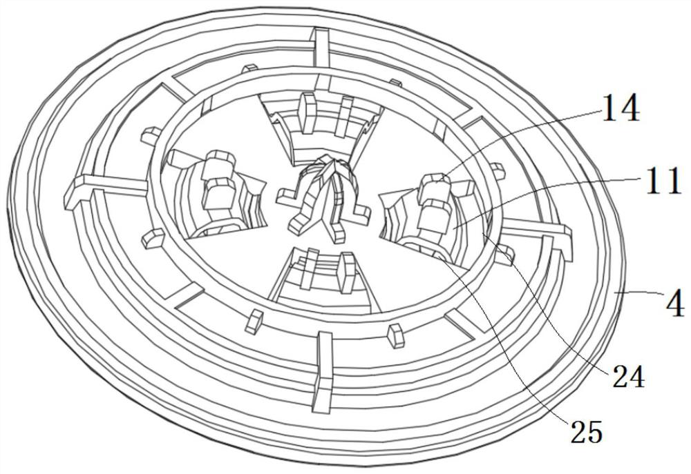
[0040] The elastic connecting body 11 includes a support portion 12 that fixes the acupuncture point toward the pressure-bearing layer 4. The support portion 12 is preferably a symmetrical structure with balanced forces on both sides, such as a platform. The two sides of the support portion 12 Both sides are connected to the filter tray 3 through the elastic part 13 . According to the different ...
PUM
 Abstract
Description
Claims
Application Information
 - R&D
- Intellectual Property
- Life Sciences
- Materials
- Tech Scout
- Unparalleled Data Quality
- Higher Quality Content
- 60% Fewer Hallucinations
Browse by: Latest US Patents, China's latest patents, Technical Efficacy Thesaurus, Application Domain, Technology Topic, Popular Technical Reports.
© 2025 PatSnap. All rights reserved.Legal|Privacy policy|Modern Slavery Act Transparency Statement|Sitemap|About US| Contact US: help@patsnap.com


