Lubricant feed mechanism for engine

a technology of lubricant feed and engine, which is applied in the direction of machine/engine, valve drive, auxillary lubrication, etc., to achieve the effect of facilitating the formation of oil passages in the oil feed member and reducing the number of components

Inactive Publication Date: 2015-05-21
TAIHO INDUSTRIES CO LTD
View PDF3 Cites 9 Cited by
  • Summary
  • Abstract
  • Description
  • Claims
  • Application Information

AI Technical Summary

Benefits of technology

[0016]The present invention provides effects as follows.
[0017]With the lubricant feed mechanism for an engine according to the present invention, lubricant is fed to a cam without using the space above the cam cap. With this configuration, interference between members is prevented, and design changes for avoiding the interference are obviated.
[0018]With the lubricant feed mechanism for an engine according to the present invention, the oil feed member is secured by using an existing bolt (a bolt for fixedly attaching the cam cap to the cylinder head). Thus, addition of a separate fastening member such as a bolt is dispense

Problems solved by technology

Hence, in actually applying the technology described in JP-A-2010-164009, the cam shower pipe may interfere with another member, such

Method used


Image

  • Lubricant feed mechanism for engine
  • Lubricant feed mechanism for engine
  • Lubricant feed mechanism for engine

Examples


first embodiment

[0039]First, description is given with reference to FIGS. 1 to 8D of a configuration of an engine 1 including a lubricant feed mechanism according to the present invention.

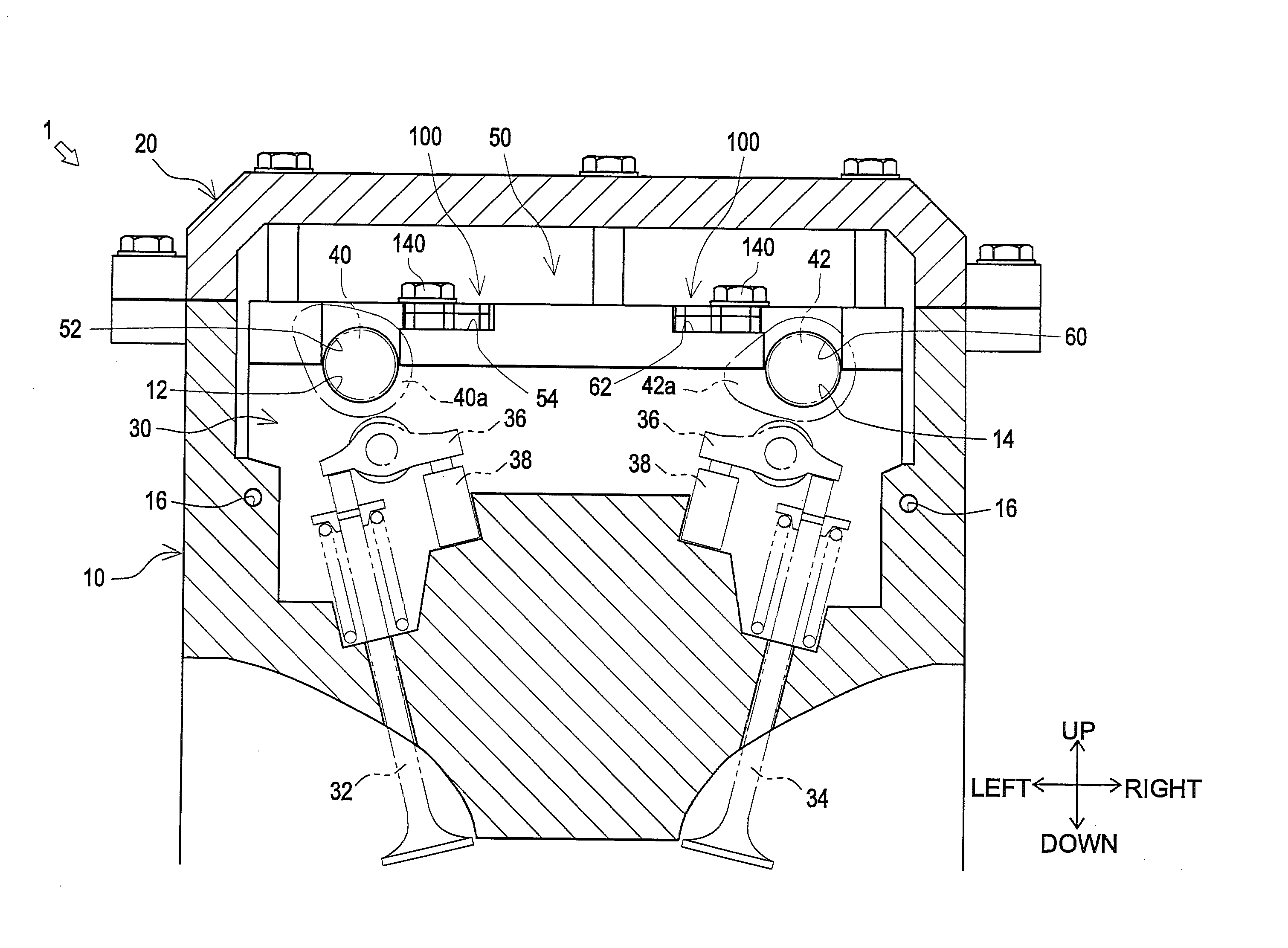
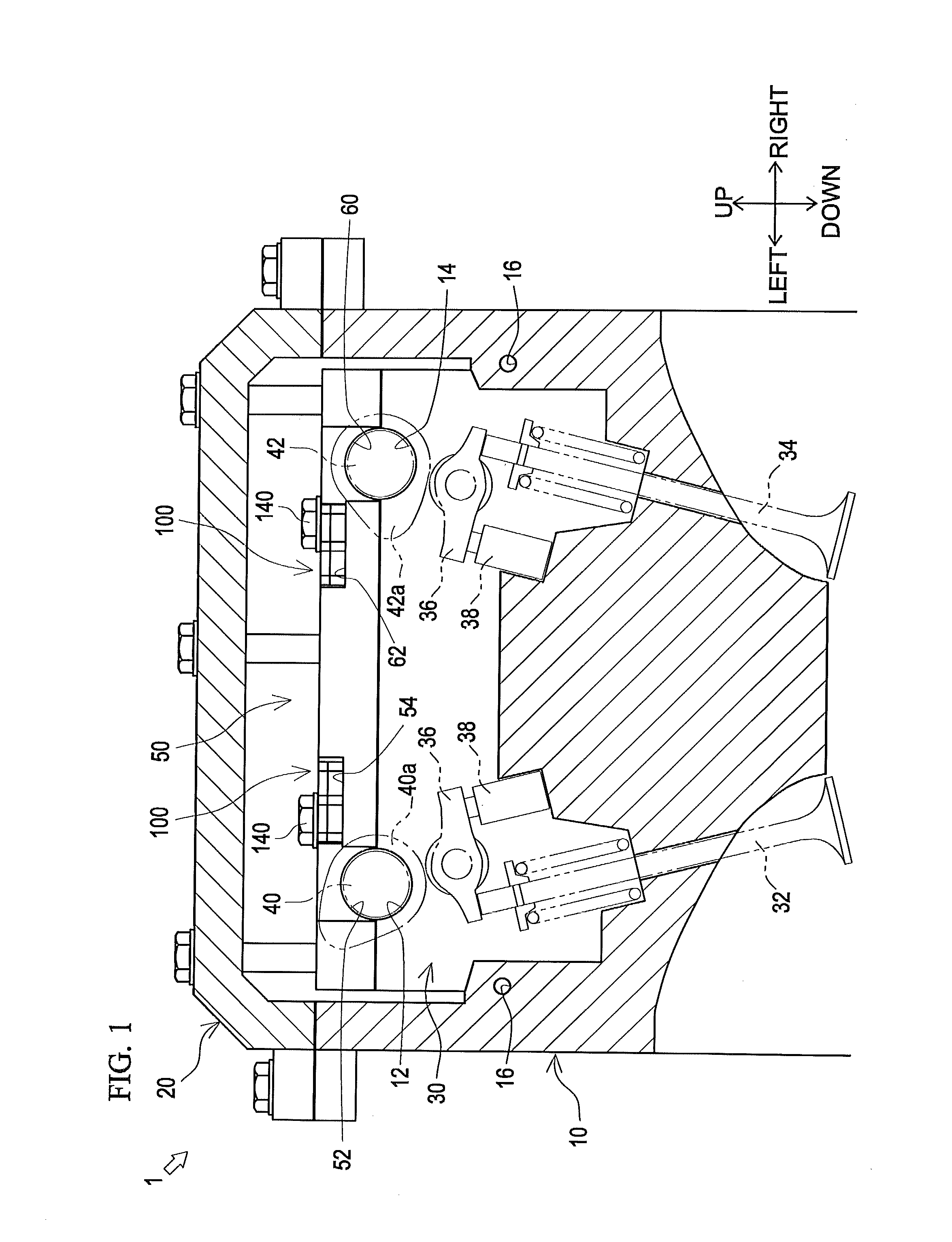
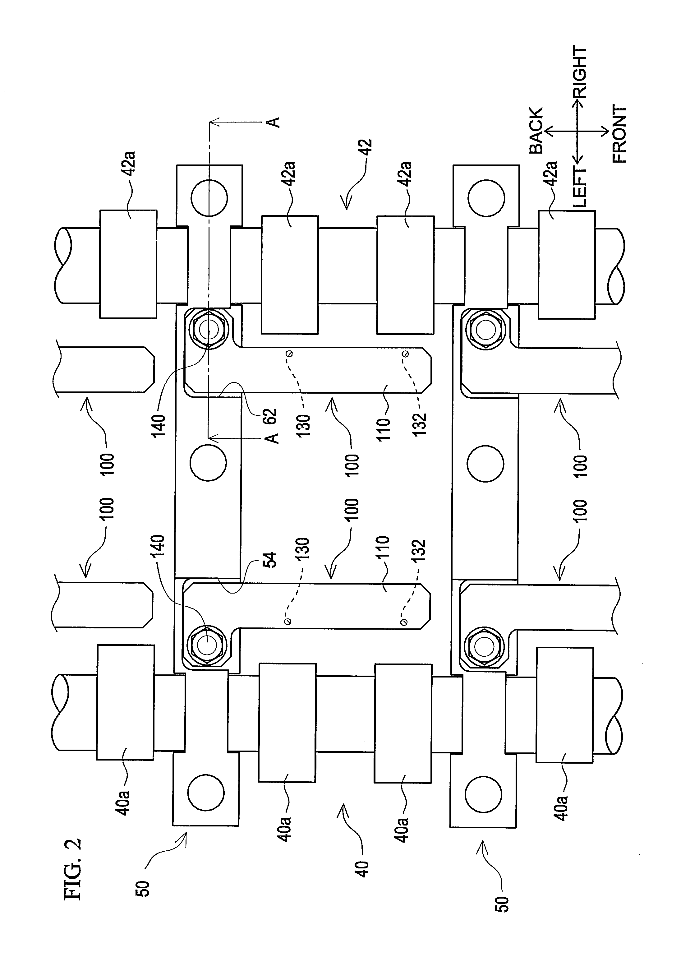
[0040]The engine 1 according to the present embodiment is an inline 4-cylinder double overhead camshaft (DOHC) 16-valve gasoline engine. Description is given below mainly focusing on one cylinder of the four cylinders arranged in the front-back direction. The engine 1 mainly includes a cylinder head 10, a cylinder head cover 20, a valve gear 30, cam caps 50, and oil feed members 100.

[0041]The cylinder head 10 depicted in FIGS. 1, 3, and 5 makes a principal structural body of the engine 1 together with a cylinder block (not shown). The cylinder head 10 is fixedly attached to an upper portion of the cylinder block (not shown). The cylinder head 10 mainly includes a bearing 12 on the intake-side, a bearing 14 on the exhaust-side, an oil gallery 16, and a cam journal oil passage 18.

[0042]The intake-side bearing 12 dep...

second embodiment

[0112]As a second embodiment, the second oil passage 126 and the third oil passage 128 provided on the second panel member 120 may, as depicted in FIGS. 11A to 11C, have any lengths, cross-sectional shapes, numbers of turns, or angles of turning that are different from each other.

[0113]Specifically, in the second panel member 120 depicted in FIGS. 11A to 11C, the second oil passage 126 is larger in cross-sectional shape, namely, is wider and deeper, than the third oil passage 128. Further, the second oil passage 126 is configured to bend more moderately than the third oil passage 128, and thus the second oil passage 126 has a shorter length than the third oil passage 128.

[0114]In this manner, the second oil passage 126 and the third oil passage 128 are shaped to be asymmetrical with respect to each other, such that lubricant fed from the first oil passage 124 takes different pressure losses when flowing in the second oil passage 126 and in the third oil passage 128, and that the flo...

third embodiment

[0115]As depicted in FIG. 12, it is conceivable as a third embodiment that the second panel member 120 located at the lowermost layer of the plurality of (two) panel members, i.e. the first panel member 110 and the second panel member 120, configuring the oil feed member 100 (in the present embodiment, on the lower side of the two panel members, i.e., on the cam cap 50 side) is integrated with the cam cap 50. Specifically, second panel members 120 are integrated with the cam cap 50 so as to extend frontward from the intake-side recess 54 and the exhaust-side recess 62 of the cam cap 50, respectively; in this manner, the cam cap 50 and the second panel members 120 are handled as a single member. This configuration facilitates management of components of the cam cap 50 and the second panel members 120 and attachment to the cylinder head 10.


PUM


Abstract

Provided is a lubricant feed mechanism for an engine in which space above a cam cap is not used. A lubricant feed mechanism for an engine is configured to feed lubricant through a cylinder head, a camshaft, and a cam cap to a cam of a valve gear. The mechanism includes an oil feed member that is disposed in the cam cap such that an upper end thereof is set at a lower level than an upper end of the cam cap in a height-wise direction and has an oil passage configured to guide lubricant to be fed through the cam cap to the cam.

Description

TECHNICAL FIELD[0001]The present invention relates to a technology of a lubricant feed mechanism for an engine for feeding lubricant to a cam of a valve gear through a cylinder head, a camshaft, and a cam cap.BACKGROUND ART[0002]A technology of a lubricant feed mechanism for an engine has been known by which lubricant is fed to a cam of a valve gear through a cylinder head, a camshaft, and a cam cap. Examples include JP-A-2010-164009.[0003]A lubricant feed mechanism for an engine described in JP-A-2010-164009 includes a cylinder head having a hearing, a camshaft rotatably supported by the bearing, a cam cap fixedly attached to the cylinder head from the upper side to hold the camshaft therewith, and a cam shower pipe connected to an upper portion of the cam cap.[0004]Further, the lubricant feed mechanism includes a communicating oil passage from an oil gallery of the cylinder head to the camshaft (bearing), an oil passage penetrating the camshaft (cam journal), and a communicating o...

Claims


Application Information

Patent Timeline
IPC IPC(8): F01M9/10
CPCF01M9/101F01M1/08F01L1/04F01M1/06F01M9/10F02F1/24
Inventor HIKITA, YASUHIRO
Owner TAIHO INDUSTRIES CO LTD
Why Eureka
Try Eureka