Cord winding structure for window blind

Inactive Publication Date: 2015-05-21
HUNG MIN CHE
View PDF43 Cites 17 Cited by
  • Summary
  • Abstract
  • Description
  • Claims
  • Application Information

AI Technical Summary

Benefits of technology

The present invention is a cord winding structure for window blind that aims to provide lower cost and higher convenience for users. It allows the cords of the window blind to be smoothly released or rewound without getting tangled easily. The structure includes a guide rod, pulleys, and a spring that work together to make the winding process easier and safer. The invention also includes a spiral spring that helps to keep the cords organized and prevents them from getting tangled. Overall, this cord winding structure provides a cost-effective and convenient solution for window blinds.

Problems solved by technology

While the conventional window blind provides the effect of adjusting indoor brightness, it has a problem in operation.
In the event the user pulls the cords with an excessive force or releases the cords too quickly, the blind might not be accurately stopped at the user's desired position.
Therefore, the conventional window blind has poor convenience in use.
Further, when the user intends to open or close the blind but applies an uneven force to pull the cords, the cords connected to the transmission unit tend to become tangled and could not be pulled smoothly.
Therefore, additional cord accessories are needed to control the cords or prevent the cords from tangling, resulting in increased use cost of the conventional window blind.
Therefore, the conventional window blind has the following disadvantages: (1) high use cost; (2) poor convenience in use; and (3) tending to cause tangled cords and accordingly unsmooth releasing and rewinding of the cords.

Method used


Image

  • Cord winding structure for window blind
  • Cord winding structure for window blind
  • Cord winding structure for window blind

Examples


Embodiment Construction

[0021]The present invention will now be described with some preferred embodiments thereof and by referring to the accompanying drawings. For the purpose of easy to understand, elements that are the same in the preferred embodiments are denoted by the same reference numerals.

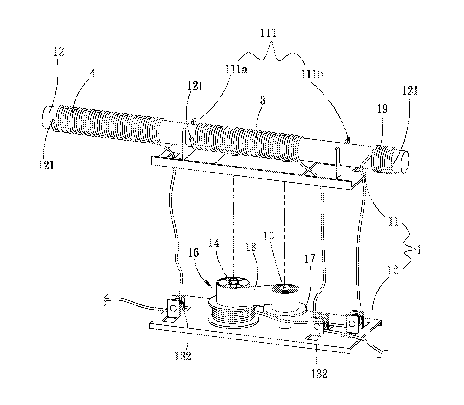
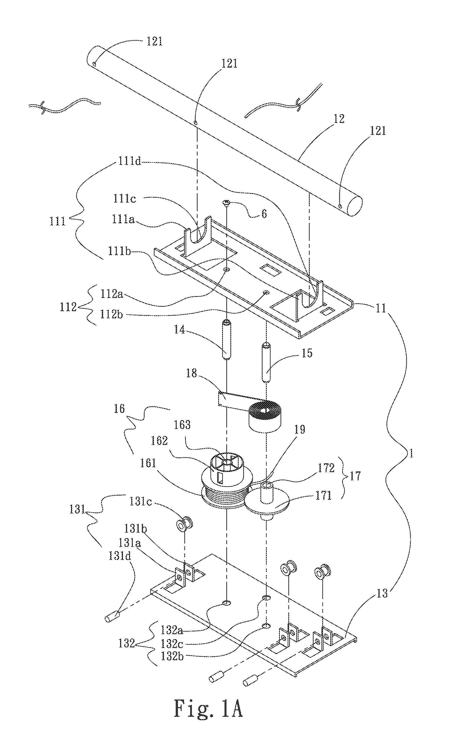
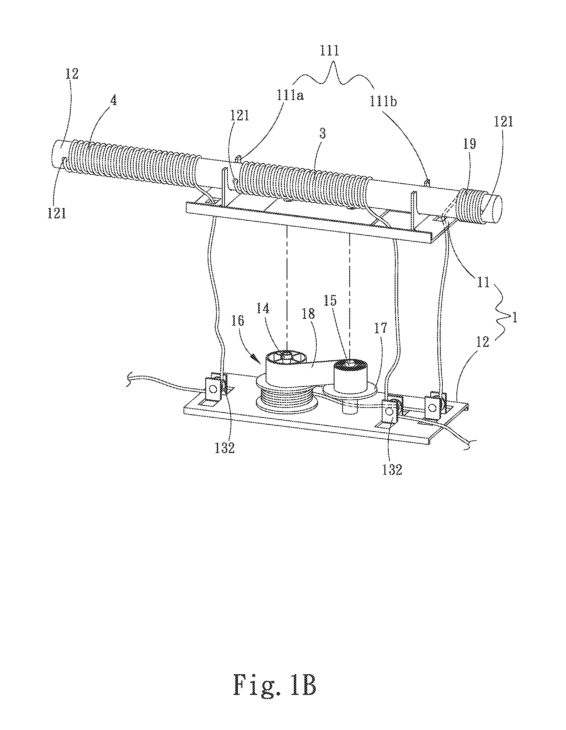
[0022]Please refer to FIGS. 1A, 1B and 1C that are exploded, partially assembled and fully assembled perspective views, respectively, of a cord winding structure for window blind according to a first preferred embodiment of the present invention. As shown, the present invention includes a cord winding assembly 1.

[0023]The cord winding assembly 1 is composed of a first plate member 11, a guide rod 12, a second plate member 13, a first shaft 14, a second shaft 15, a first guiding wheel 16, a second guiding wheel 17, a first spiral spring 18, and a first cord 19.

[0024]The first plate member 11 is provided with a guide rod support bracket unit 111, which is upward projected from one side of the first plate member 11,...


PUM


Abstract

A cord winding structure for window blind includes a cord winding assembly composed of a first and a second plate member, a guide rod, a first and a second shaft, a first and a second guiding wheel, and a spiral spring. The first plate member has a guide rod support bracket unit upward projected from one side thereof for supporting the guide rod thereon. The second plate member has a plurality of pulley sets provided thereon. The first and second guiding wheels are rotatably connected to between the first and the second plate member via the first and the second shaft, respectively. The spiral spring is fitted to one side of the second guiding wheel with an end extended to fasten to the first guiding wheel. A first cord is wound around the guide rod, the pulley sets and a first cord receiving groove of the first guiding wheel.

Description

This application claims the priority benefit of Taiwan patent application number 102142226 filed on Nov. 20, 2013.FIELD OF THE INVENTION[0001]The present invention relates to a window blind, and more particularly to a cord winding structure for window blind that has lower use cost and allows cords of the window blind to be released or rewound smoothly without the risk of becoming tangled easily.BACKGROUND OF THE INVENTION[0002]A window blind is mounted on a window to block sun light from directly entering a room and therefore makes the room more comfortable. When the light in the room is insufficient, the window blind can be opened to increase the brightness in the room. Further, the window blind can also be used to protect the users' privacy and decorate the room.[0003]Conventionally, a window blind includes a blind, a transmission unit, and a plurality of cords. The transmission unit is located on a top of the blind and is connected to the cords, and the blind is connected to the ...

Claims


Application Information

Patent Timeline
IPC IPC(8): E06B9/322B65H75/44
CPCE06B9/322E06B2009/3225B65H75/4402
Inventor HUNG, MIN-CHE
Owner HUNG MIN CHE
Why Eureka
Try Eureka