
Securing mechanism

Active Publication Date: 2015-05-21
WISTRON CORP
View PDF17 Cites 1 Cited by
  • Summary
  • Abstract
  • Description
  • Claims
  • Application Information

AI Technical Summary

Benefits of technology

The present invention provides a securing mechanism that allows for easy mounting and dismounting of an electronic device using only one hand. This mechanism does not require the user's hand to enter the mounting frame for grabbing the electronic device and is efficient in facilitating the mounting and dismounting process.

Problems solved by technology

Therefore, mounting and dismounting processes of the electronic device are not only inconvenient but also time-consuming.
However, during the mounting or the dismounting process of the electronic device with the above-mentioned conventional tool-less securing mechanism, the user must use both hands to respectively operate the securing mechanism and the electronic device, which is relatively inconvenient.
For a server that has a complex internal structure, it is even more difficult to locate the electronic device and to perform the operation within the constraints of the mounting frame.
In addition, the conventional securing mechanism generally does not fit with a variety of electronic devices of different sizes.

Method used


Image

  • Securing mechanism
  • Securing mechanism
  • Securing mechanism

Examples


Embodiment Construction

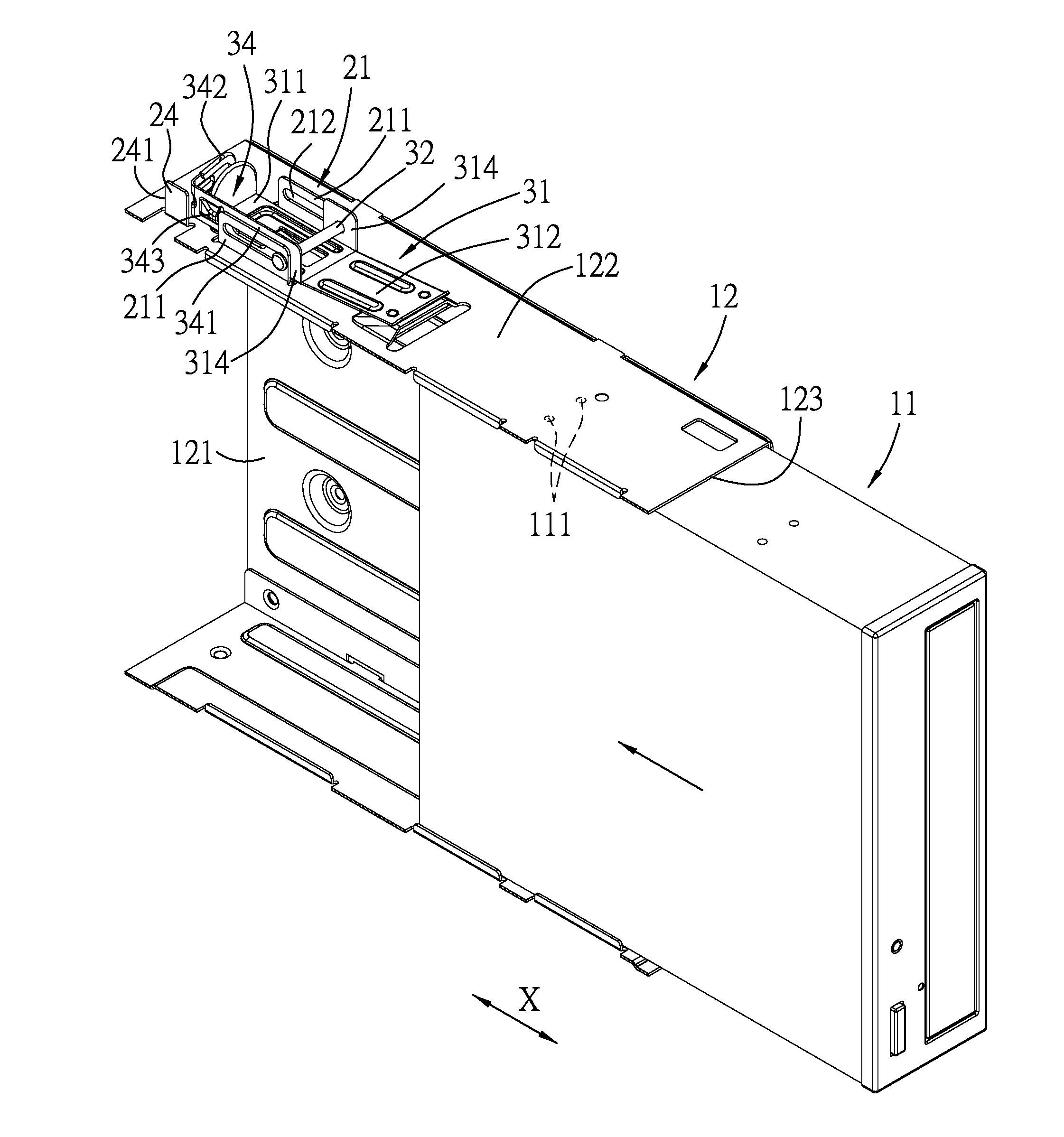
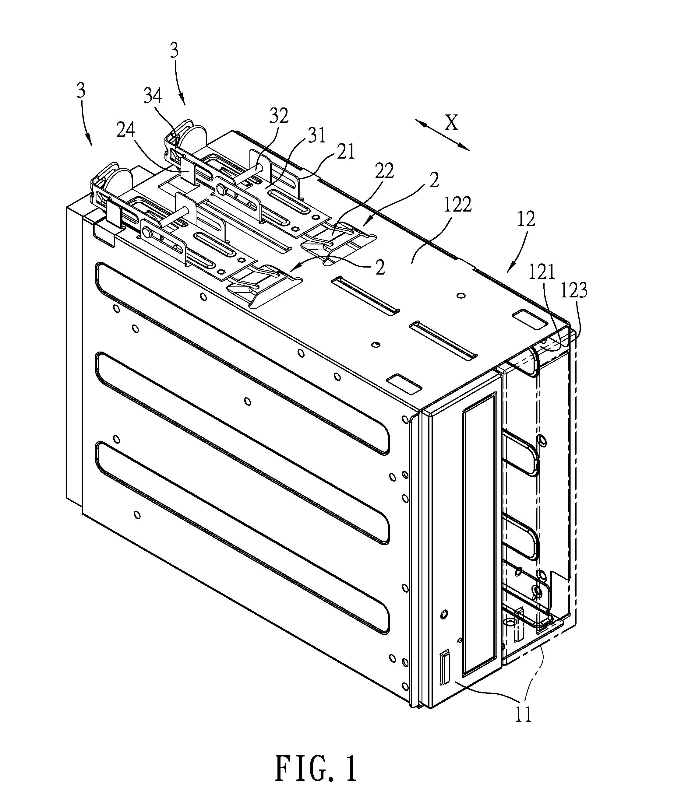
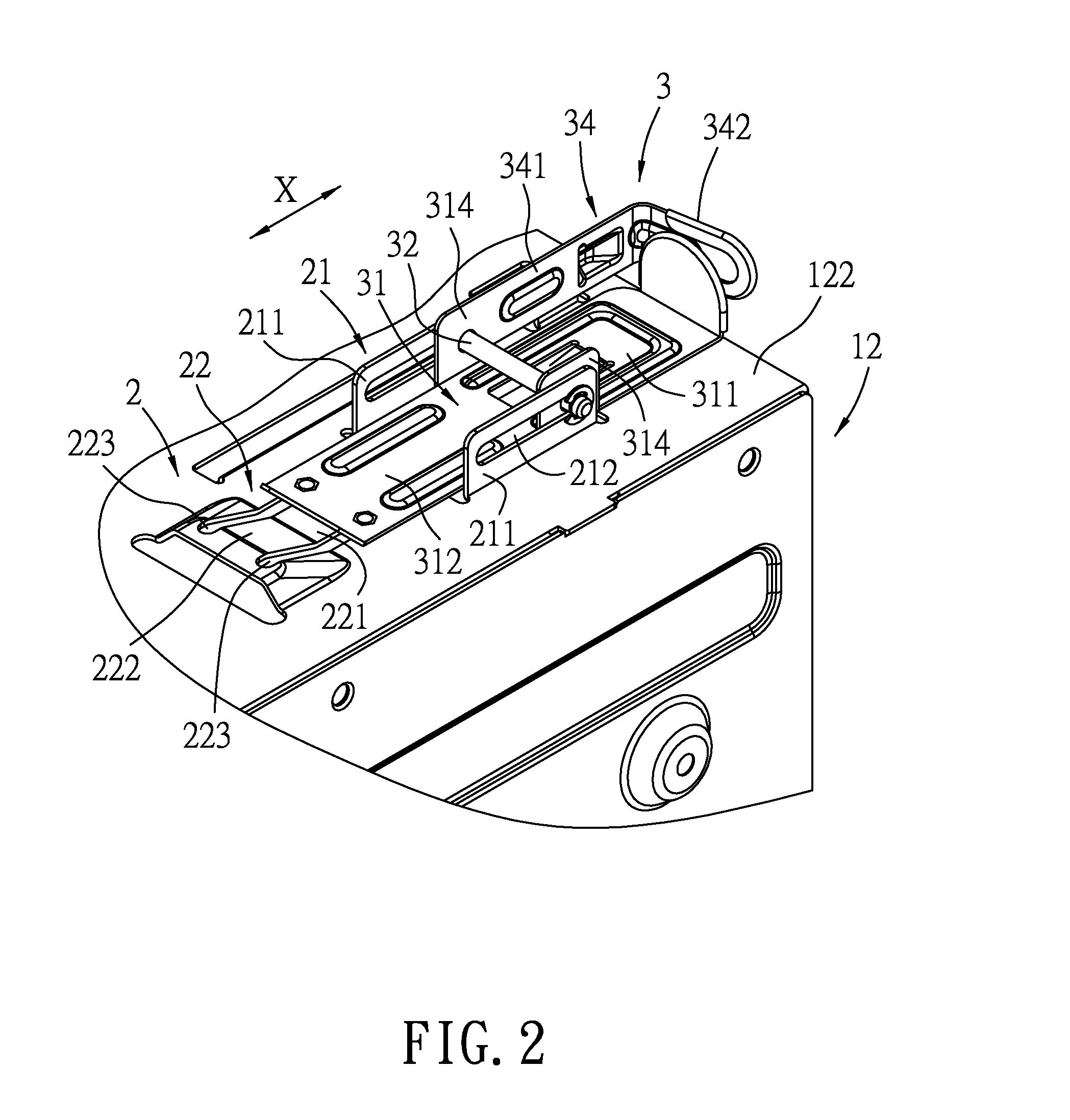
[0030]FIG. 1 shows an embodiment of a securing mechanism according to the present invention. The securing mechanism is adapted for fixing two electronic devices 11 to a mounting frame 12. The mounting frame 12 defines an accommodating space 121, and has a lateral plate 122 and an opening 123 that communicates the accommodating space 121. Each of the electronic devices 11 is able to be inserted into or pulled out from the accommodating space 121 through the opening 123 in an insertion direction (X) that is parallel to the lateral plate 122, and is formed with two fixing holes 111 that face the lateral plate 122 (see FIG. 6). In this embodiment, the electronic device 11 is an optical disc drive (ODD), but the configuration of the electronic device 11 is not limited thereto. The securing mechanism includes two rail units 2 that are parallel to each other and that are spaced apart from each other in a first direction perpendicular to the insertion direction (X), and two locking units 3 ...


PUM


Abstract

A securing mechanism includes a rail unit and a locking unit. The rail unit has a first rail structure, a guiding surface that is formed with a pin extension slot, and a first engaging structure. The locking unit has a fixing pin protruding into the pin extension slot, a second rail structure cooperating with the first rail structure to move the locking unit between an unlocked position, where the fixing pin is away from a fixing hole of the electronic device and where the first engaging structure is separated from the second engaging structure, and a locked position, where the fixing pin engages the fixing hole of the electronic device and where the second engaging structure engages the first engaging structure for fixing the electronic device to a mounting frame.

Description

CROSS-REFERENCE TO RELATED APPLICATION[0001]This application claims priority of Chinese Patent Application No. 201320725394.8, filed on Nov. 15, 2013, the disclosure of which is incorporated herein by reference.BACKGROUND OF THE INVENTION[0002]1. Field of the Invention[0003]This invention relates to a securing mechanism, more particularly to a securing mechanism that is capable of securing an electronic device.[0004]2. Description of the Related Art[0005]Conventionally, when an electronic device (e.g., an optical disc drive) needs to be mounted to a server or a personal computer, a securing member (e.g., a screw) is often used so as to lock the electronic device to a mounting frame of the server or the personal computer. When applying the screw in the locking process, a tool (e.g., a screwdriver) is required. Therefore, mounting and dismounting processes of the electronic device are not only inconvenient but also time-consuming. As a result, a tool-less securing mechanism has been d...

Claims


Application Information

Patent Timeline
IPC IPC(8): H05K5/02
CPCH05K5/0221G11B33/124G11B33/128G06F1/187
Inventor MO, HAN-JUN
Owner WISTRON CORP
Learn More