Tool for mounting and dismounting pipe clamp

a technology for mounting and dismounting tools and pipe clamps, which is applied in the field of tools, can solve problems such as inconvenience in us

Active Publication Date: 2018-09-13
YANG JEN YUNG
View PDF34 Cites 2 Cited by
  • Summary
  • Abstract
  • Description
  • Claims
  • Application Information

AI Technical Summary

Benefits of technology

[0011]To avoid unexpected release of the retaining member, a second elastic element is disposed between the retaini

Problems solved by technology

However, according to the driving manner through rotation of a threaded rod, a long rotation distance is required to achieve a desir

Method used


Image

  • Tool for mounting and dismounting pipe clamp
  • Tool for mounting and dismounting pipe clamp
  • Tool for mounting and dismounting pipe clamp

Examples


Embodiment Construction

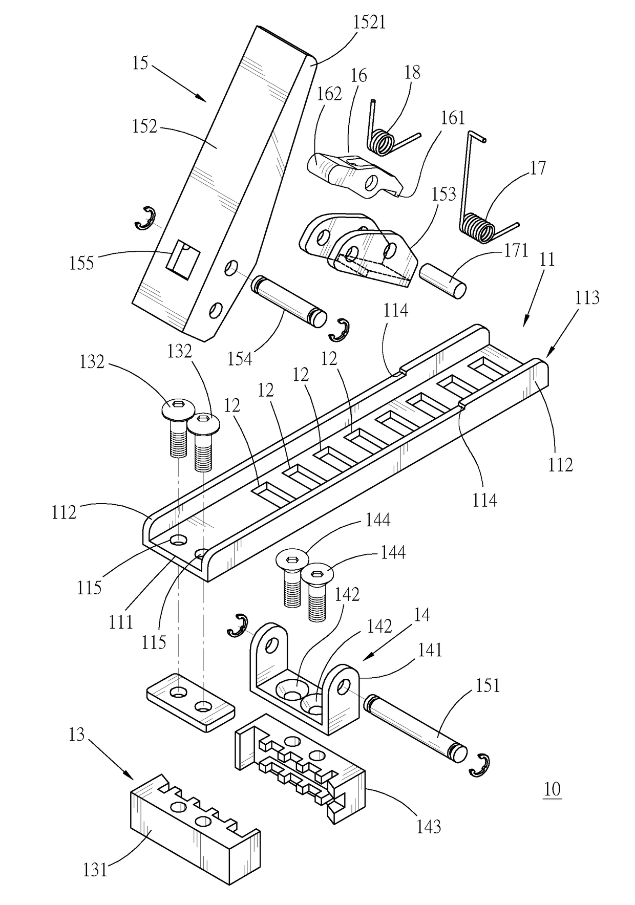
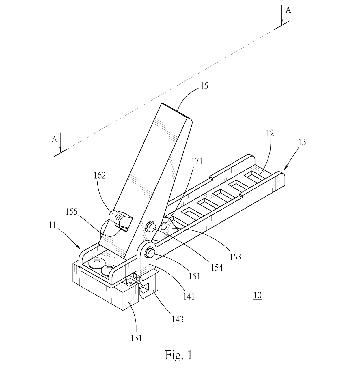
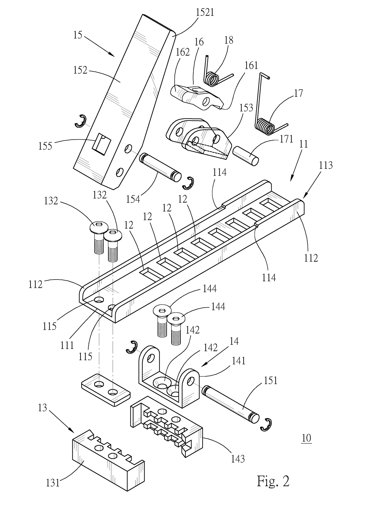
[0017]Firstly, referring to FIG. 1 and FIG. 2, a tool (10) for mounting and dismounting a pipe clamp provided by a preferred embodiment of the present creation mainly includes abase (11), a plurality of positioning portions (12), a first end portion (13), a second end portion (14), an operating member (15), a retaining member (16), a first elastic element (17), and a second elastic element (18).

[0018]The base (11) has an approximately rectangular base plate (111). A guide portion (113) formed by two parallel side plates (112) linearly extends along the long axis of the base plate (111), and protrudes from two sides of the long axis of the base plate (111). Two stop shoulder surfaces (114) are separately disposed on the side plates and are perpendicularly corresponding to the long axis of the base plate (111). Two joining holes (115) penetrate in parallel through one end of the long axis of the base plate (111).

[0019]The positioning portions (12) are holes respectively penetrating th...


PUM


Abstract

In a tool for mounting and dismounting a pipe clamp provided by the present creation, a first end portion and a movable second end portion are separately disposed on a base, and a connecting rod mechanism is used to convert circular motion into linear motion of the second end portion by force, so as to reduce the distance between the second end portion and the first end portion, thereby achieving an effect that the annular inner diameter of a pipe clamp is increased when the pipe clamp is held between the first end portion and the second end portion.

Description

BACKGROUND OF THE INVENTION1. Field of the Invention[0001]The present creation relates to a tool, and more particularly to a tool for mounting and dismounting a pipe clamp.2. Description of the Related Art[0002]To properly fix joint parts of pipelines, a generally used method is to bind and fix the joint parts by using elastic hand-pressing pipe clamps. A large force is required to be applied on a hand-pressing pipe clamp to increase its annular inner diameter for mounting or dismounting. To facilitate the mounting and dismounting operation, several clamp tool technologies of different designs are disclosed in the prior art.[0003]Specifically, as disclosed by a Chinese utility model patent No. M484497 in the prior art, the distance between a movable end and a fixed end is changed through rotation of a threaded rod, so as to change the inner diameter of a hand-pressing pipe clamp to facilitate mounting or dismounting. However, according to the driving manner through rotation of a thr...

Claims


Application Information

Patent Timeline
IPC IPC(8): F16L55/00B25B7/12F16L21/06
CPCF16L55/00F16L21/06B25B7/12
Inventor YANG, JEN-YUNG
Owner YANG JEN YUNG
Why Eureka
Try Eureka