
Hammer for a horizontal shaft impact crusher

a horizontal shaft and impact crusher technology, applied in the field of rotor hammers, can solve the problems of operator fingers being trapped during installation and removal, significant health and safety risks, and restricted access to the sides of elongated hammers, so as to facilitate the mounting and dismounting of crusher hammer elements, reduce and eliminate

Active Publication Date: 2020-06-30
SANDVIK INTELLECTUAL PROPERTY AB
View PDF15 Cites 0 Cited by
  • Summary
  • Abstract
  • Description
  • Claims
  • Application Information

AI Technical Summary

Benefits of technology

[0004]It is an objective of the present invention to facilitate mounting and dismounting crusher hammer elements at an impeller of a HSi-crusher. It is a further specific objective to provide a hammer mountable at a rotor of a HSi-crusher that is capable of being mounted and suspended from a lifting device and / or auxiliary lifting tool such as a crane and the like to enable the hammer to be manipulated and in particular rotated at a suitable lifting device during mounting and dismounting procedures. It is a further objective to reduce and eliminate, as far as possible, the health and safety risks to which operating personnel are exposed during hammer mounting and dismounting procedures so as to avoid specifically injuries to an operator's hands and fingers. It is yet a further objective to enable hammer parts to be raised and lowered substantially vertically at a HSi-crusher to avoid or minimise a need for access to the lateral sides of the crusher during such procedures.
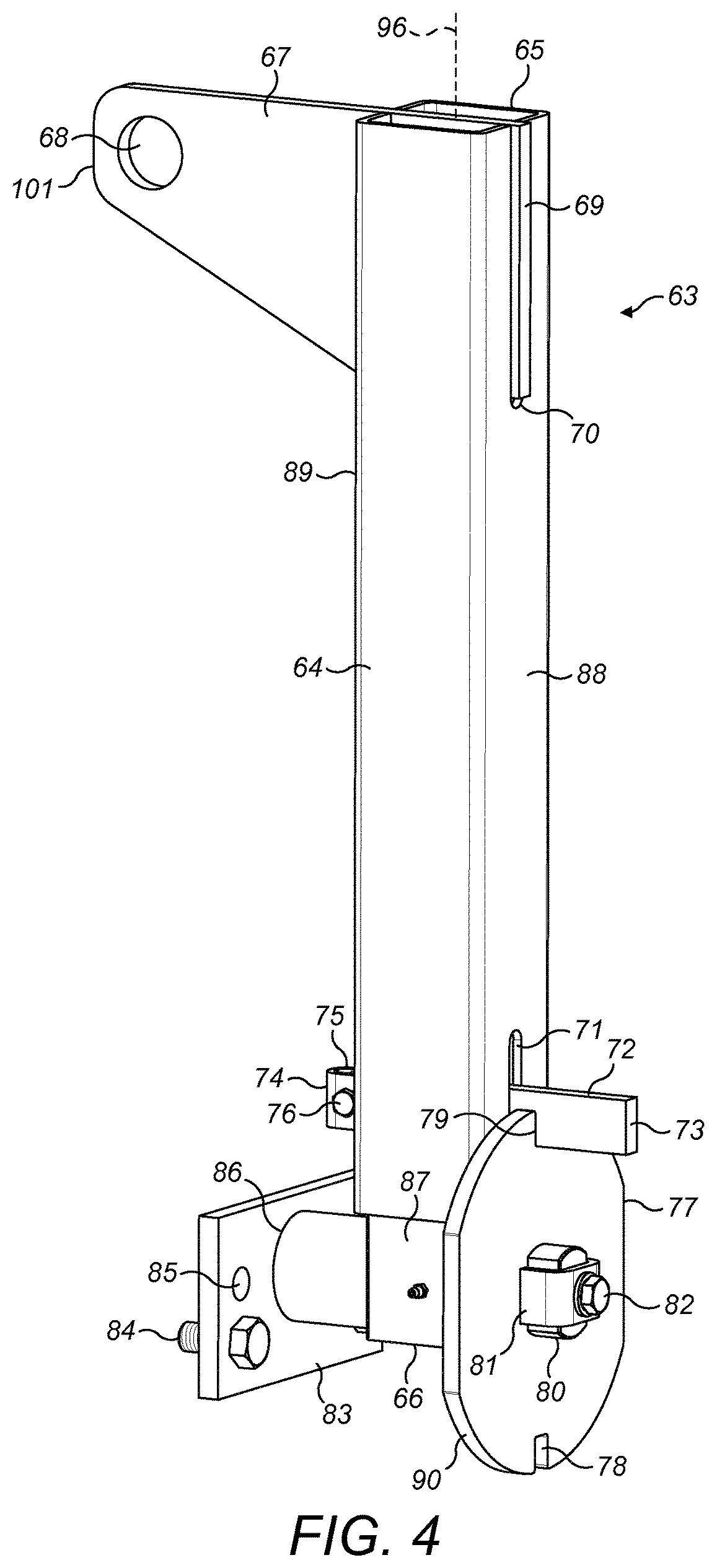
[0005]The objectives are achieved via a hammer that is configured specifically for mounting at a lifting device via contact with a front face of the hammer. Advantageously, the hammer comprises at least one bore to receive an attachment, optionally in the form of threaded bolt, to couple the hammer releasably to the lifting device. Suspending the hammer at the lifting device via its front face is beneficial to greatly facilitate mounting and dismounting the hammer at the rotor where access and available space is typically restricted. Additionally, the present hammer is capable of being supported from a position vertically above by the lifting device as the locking wedges are moved into either engaging or disengaging contact with the hammer at the rotor. This is achieved specifically by attachment to the lifting device via the hammer front face. Once the hammer is secured via the locking wedges, the lifting device may be conveniently disengaged from the hammer. Accordingly, the present hammer configuration avoids the need for personnel to physically hold the hammer in position as the locking wedges are either engaged or disengaged. The risk of trapping an operator's hands or fingers is therefore greatly reduced or eliminated.
[0006]Advantageously, the present hammer is conveniently and reliably attachable to a lifting device such that the hammer part, once attached, may be held and rotated in a suspended ‘floating’ position such that an operator may manipulate conveniently the hammer part and rotated it about an axis aligned transverse or perpendicular to the vertical (upward and downward) lifting direction by which the hammer part is introduced to or removed from the crusher rotor.
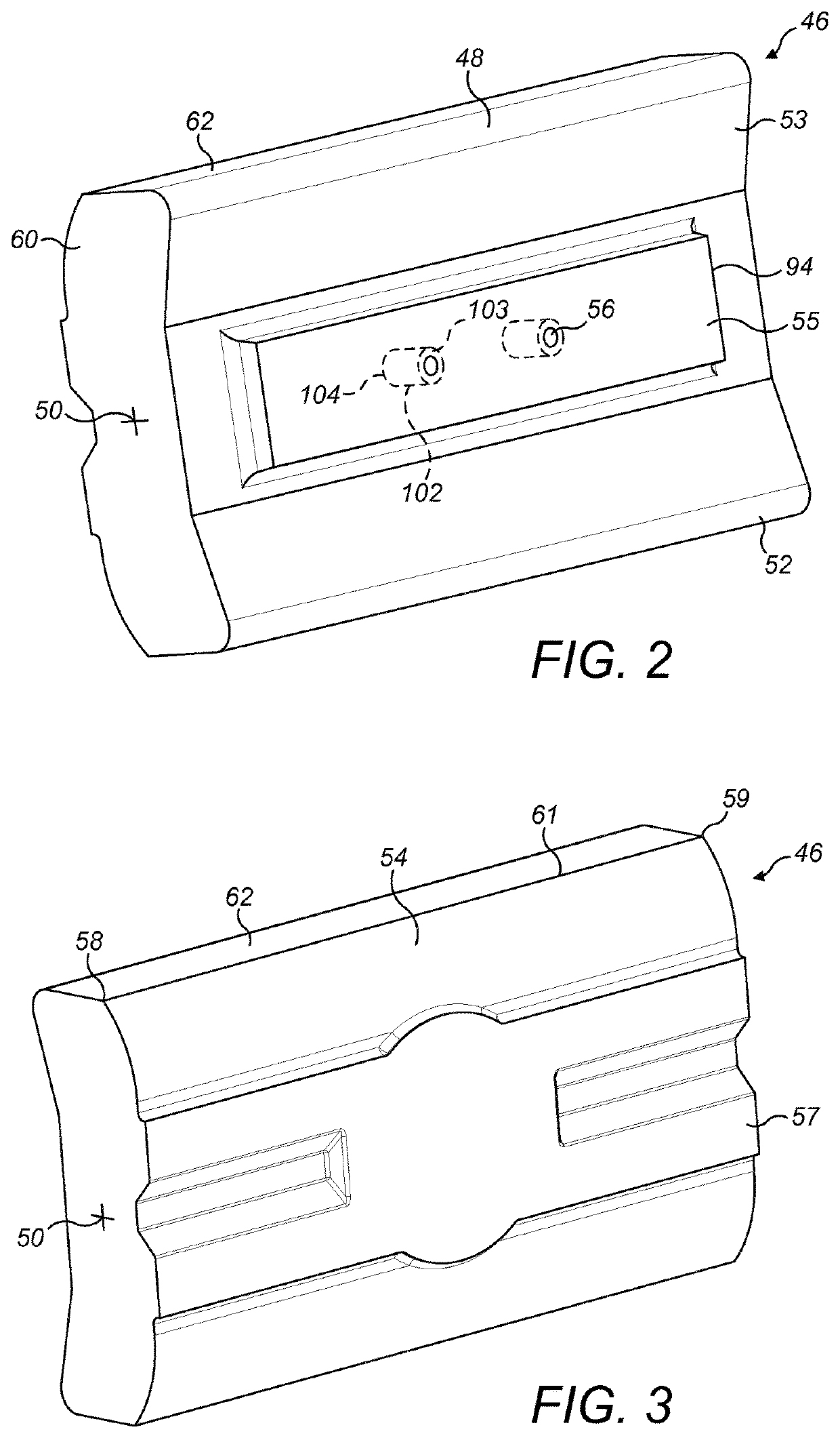
[0012]Optionally, the hammer further comprises a mount projection extending outwardly from a front face side of the main body, the at least one recess extending into the mount projection. Optionally, the mount projection is substantially rectangular and extends lengthwise between the length ends of the main body. The mount projection facilitates mounting and dismounting of the hammer at a lifting device by providing a raised plateau region having a substantially planar contact face that may be mated in close touching contact with a corresponding flat or planar mount face of a lifting device attachment bracket.
[0014]Preferably, the hammer further comprises at least one insert embedded to extend inwardly from the front face of the main body, the insert comprising the at least one recess. Preferably, the insert is formed integrally with the main body as the main body is cast formed. The present hammer is preferably formed from a casting process in which a flowable metal is introduced into a mould and allowed to solidify. The inserts may be conveniently supported within the mould during introduction and settling of the flowable metal so as to be locked and formed integrally within the cast main body. Advantageously only an end surface of the insert is exposed in the resulting as-formed cast hammer such that the inserts are effectively fused to the main body and extend inwardly into the main body (or projection) from the front face. Optionally, the insert comprises a flange that extends radially outward from a main body of the insert. The flange may comprise one or a plurality of arms (e.g., two) extending from the insert main stem. This flange is advantageous to ensure that the insert is held firmly by the metal which solidifies around it such that when pressure is applied in use (i.e., via the tightening of attachment bolts) the insert cannot move axially or radially within the casting.

Problems solved by technology

Such an arrangement is often problematic as access to the sides of the elongate hammers is restricted.
Additionally, due to the appreciable size and weight of the hammer elements interchange at the impeller carries significant health and safety risks as it is typically required to manually manipulate the hammers into or from their impeller mounted position.
Accordingly it is not uncommon for operator fingers to become trapped during installation and removal.

Method used


Image

  • Hammer for a horizontal shaft impact crusher
  • Hammer for a horizontal shaft impact crusher
  • Hammer for a horizontal shaft impact crusher

Examples


Embodiment Construction

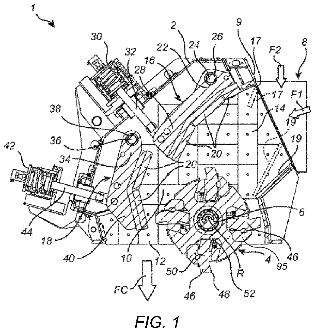
[0028]Referring to FIG. 1 a horizontal shaft impact crusher 1 (HSi-crusher) comprises a housing 2 in which an impeller indicated generally by reference 4 is rotatably mounted. A motor, (not illustrated) is operative for rotating a horizontal shaft 6 on which the impeller 4 is mounted. As an alternative to impeller 4 being fixed to shaft 6, impeller 4 may rotate around shaft 6. In either case, impeller 4 is operative for rotating around a horizontal axis, coaxial with the centre of shaft 6.

[0029]Material to be crushed is fed to a feed chute 8, which is mounted to an inlet flange 9 of housing 2, and enters a crushing chamber 10 positioned inside the housing 2 and at least partly enclosing impeller 4. Material crushed within the crusher 1 exits the crushing chamber 10 via a crushed material outlet 12. Housing 2 is provided with a plurality of interior wear protection plates 14 operative for protecting the interior of crushing chamber 10 from abrasion and impact by the material to be cr...


PUM

PropertyMeasurementUnit
particle sizeaaaaaaaaaa

Abstract

A hammer mountable at a rotor of a horizontal shaft impact crusher (HSi-crusher), the hammer including a front face, a rear face and at least one recess projecting inwardly into a main body of the hammer from the front face. The at least one recess being arranged to receive an attachment element to mount the hammer at a hammer lifting device.

Description

FIELD OF INVENTION[0001]The present invention relates to a rotor hammer and a method of manufacturing the same, and in particular although not exclusively, to a hammer having a recess extending into its main body from a front face for mounting to a hammer lifting device.BACKGROUND ART[0002]Horizontal shaft impact crushers (HSi-crushers) are utilized in many applications for crushing hard material, such as pieces of rock, ore etc. A HSi-crusher comprises a crushing chamber housing an impeller (alternatively termed a rotor) that is driven to rotate about a horizontal axis. Pieces of rock are fed towards the impeller and are struck by impeller mounted hammer elements. The rock pieces are disintegrated initially by striking contact with the hammer elements and are then accelerated and thrown against breaker plates (typically referred to as curtains) to provide further disintegration. The action of the impeller causes the material fed to the horizontal shaft impact crusher to move freely...

Claims


Application Information

Patent Timeline
Patent Type & Authority Patents(United States)
IPC IPC(8): B02C13/28B22D25/02B22D19/06B02C13/31B02C13/26
CPCB22D25/02B22D19/06B02C13/2804B02C13/31B02C2013/29
Inventor DALLIMORE, ROWANKJAERRAN, KNUTFORSBERG, ANDREAS
Owner SANDVIK INTELLECTUAL PROPERTY AB
Learn More