Tilt prevention structure for test seat

Inactive Publication Date: 2017-09-28
GIGA SOLUTION TECH
View PDF6 Cites 0 Cited by
  • Summary
  • Abstract
  • Description
  • Claims
  • Application Information

AI Technical Summary

Benefits of technology

[0006]A major objective of the present invention therefore is

Problems solved by technology

As such, the prior art's va

Method used


Image

  • Tilt prevention structure for test seat
  • Tilt prevention structure for test seat
  • Tilt prevention structure for test seat

Examples


Embodiment Construction

[0017]The following descriptions are exemplary embodiments only, and are not intended to limit the scope, applicability or configuration of the invention in any way. Rather, the following description provides a convenient illustration for implementing exemplary embodiments of the invention. Various changes to the described embodiments may be made in the function and arrangement of the elements described without departing from the scope of the invention as set forth in the appended claims.

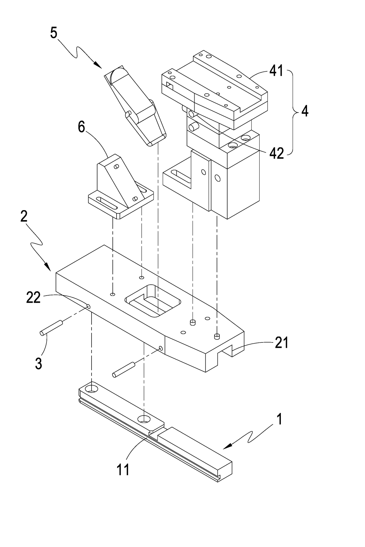
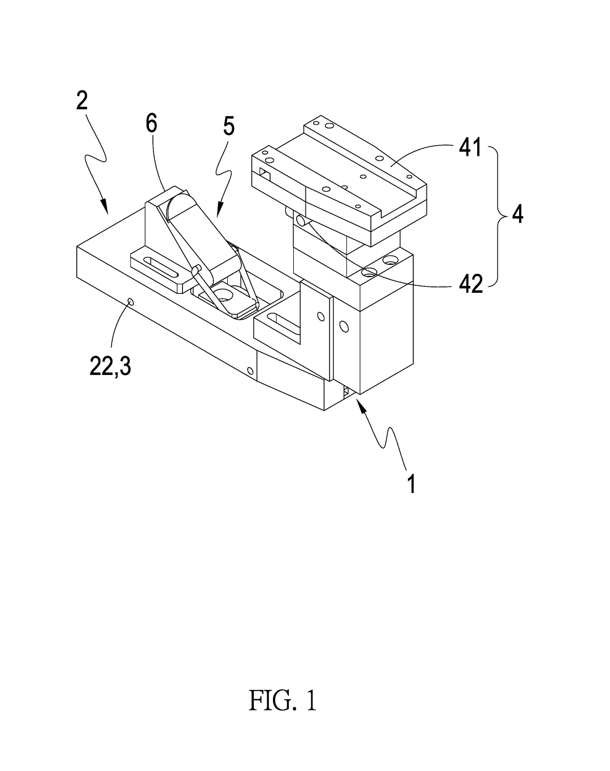
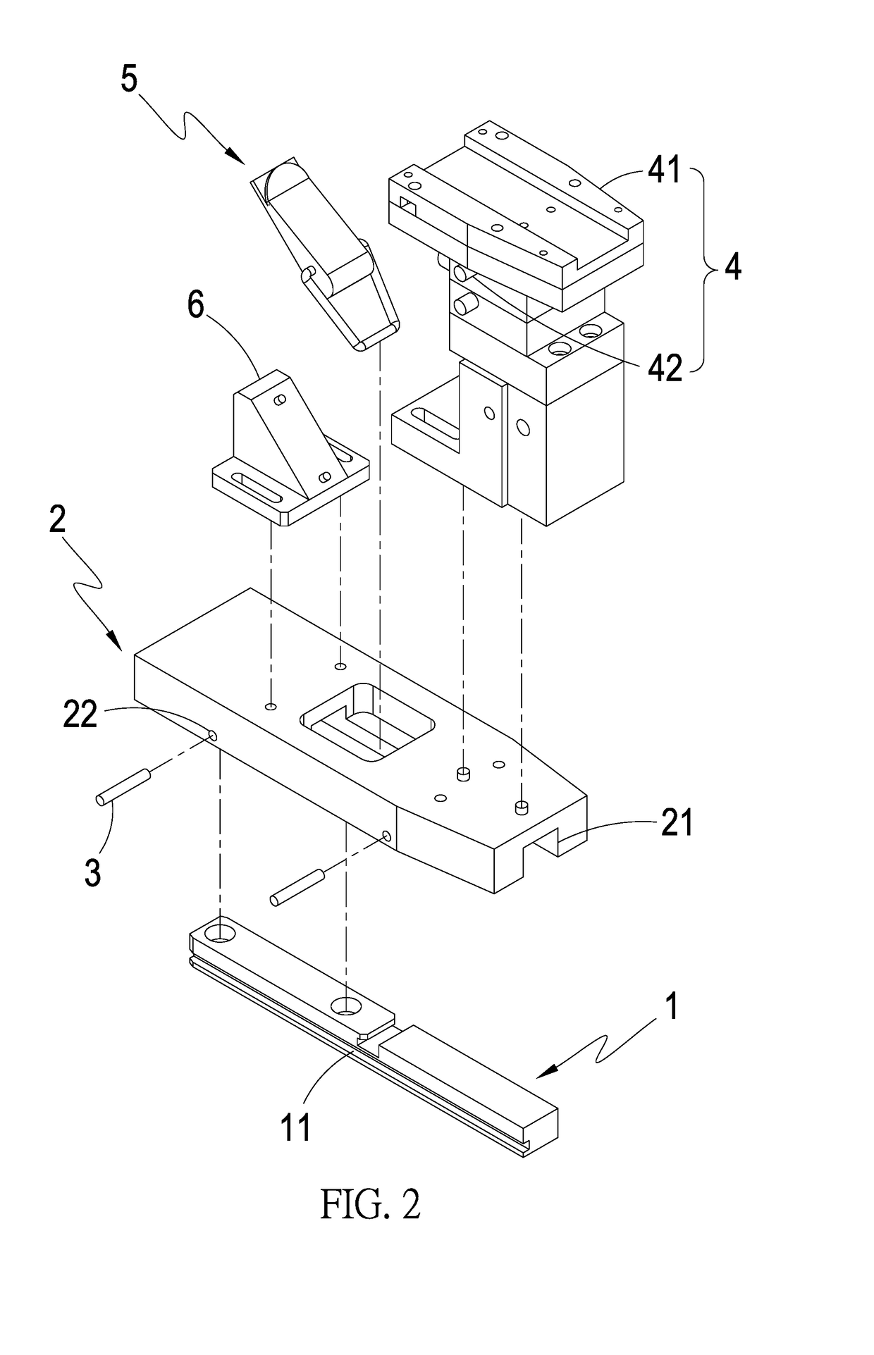
[0018]As shown in FIGS. 1 and 2, a tilt prevention structure for a test seat according to an embodiment of the present invention contains an elongated track element 1 and a base member 2. The track element 1 is fixedly configured on a test apparatus (not shown). The track element 1 has at least a notch 11 configured on a top side of the track element 1 perpendicular to an axial direction of the track element 1. The base member 2 has an elongated trough 21 along the axial direction on a bottom side s...


PUM


Abstract

The tilt prevention structure for a test seat contains a track element having at least a notch configured on a top side of the track element, a base member having a trough on a bottom side for detachably accommodating the track element and at least a fastening hole on a front side connecting the trough, and at least a limiting element plugged into the fastening hole. The track element is fixedly configured on a test apparatus. The base member is then joined to the track element by embedding the track element in the trough. The limiting elements are plugged into the fastening holes so as to prevent the base member from tilting. The base member can be moved along the track element so as to align the adjustment member against an object to be tested.

Description

BACKGROUND OF THE INVENTION[0001](a) Technical Field of the Invention[0002]The present invention is generally related to test seats, and more particular to a tilt prevention structure for a test seat.[0003](b) Description of the Prior Art[0004]A production line has a specific process running sequentially through a number of workstations. If a work in progress (WIP) is delayed at a workstation, the subsequent workstations will be idle and the process has to be speeded up afterwards.[0005]A test seat in the above production process is a device designed to hold the WIP under test in place and allow it to be tested by other test apparatus. In order to hold the WIP reliably, a conventional test seat has to be fixedly positioned. Since the test seat has a certain weight and length, usually an operator has to hold the test seat with one hand and position the test seat with the other hand, so as to prevent the test seat from tilting and damaging the WIP. This is a time consuming work, espec...

Claims


Application Information

Patent Timeline
IPC IPC(8): F16M13/02B25B11/00
CPCB25B11/00F16M13/022B23Q1/0063B23Q3/103
Inventor CHU, YU-CHUANCHEN, LIANG-PO
Owner GIGA SOLUTION TECH
Why Eureka
Try Eureka