Electric power transport system comprising a cold dielectric superconducting cable

a technology of cold dielectric superconducting cable and power transport system, which is applied in the manufacture/treatment of superconducting devices, superconducting magnets/coils, electrical apparatus, etc., can solve the problems of increased installation time and additional expenses of the plant, and achieve the effect of avoiding thermal insulation leakage, preventing leakage, and reducing the force applied to the inner gask

Inactive Publication Date: 2008-04-15
PRYSMIAN CAVI E SISTEMI ENERGIA
View PDF9 Cites 13 Cited by
  • Summary
  • Abstract
  • Description
  • Claims
  • Application Information

AI Technical Summary

Benefits of technology

[0018]The Applicant perceived that the problem of controlling such a pressure difference might be solved with a system apt to limit the cryogenic fluid leakages from the flowing channel, and to prevent the infiltration of such leakages into said under vacuum gap. Said system ensures the vacuum preservation inside the cryostat, and avoids the damaging of the thermal insulator. Moreover, the Applicant perceived that the advantages provided by said system are partly related to the fact of subdividing the pressure difference between the internal volume of the cryostat and the cryogenic fluid flowing channel into two different gradients.
[0019]In particular, the Applicant found that interposing between two cryostat modules at least two gaskets arranged one inside the perimeter of the other, and connecting the zone between said at least two gaskets with the environment external to the cryostat, the potential cryogenic fluid leakages from the flowing channel are brought outside the cryostat, thus preventing the risk of infiltrations of said fluid in said cryostat gap causing vacuum loss.
[0020]In addition, the presence of at least two gaskets subdivides the total pressure difference applied between said under vacuum gap and said cryogenic fluid flowing channel in at least two gradients, thus decreasing the force applied on the inner gasket, with benefit for the seal and reliability of the same.

Problems solved by technology

This entails additional expenses and longer setting up times for the plant, too.

Method used


Image

  • Electric power transport system comprising a cold dielectric superconducting cable
  • Electric power transport system comprising a cold dielectric superconducting cable
  • Electric power transport system comprising a cold dielectric superconducting cable

Examples


Embodiment Construction

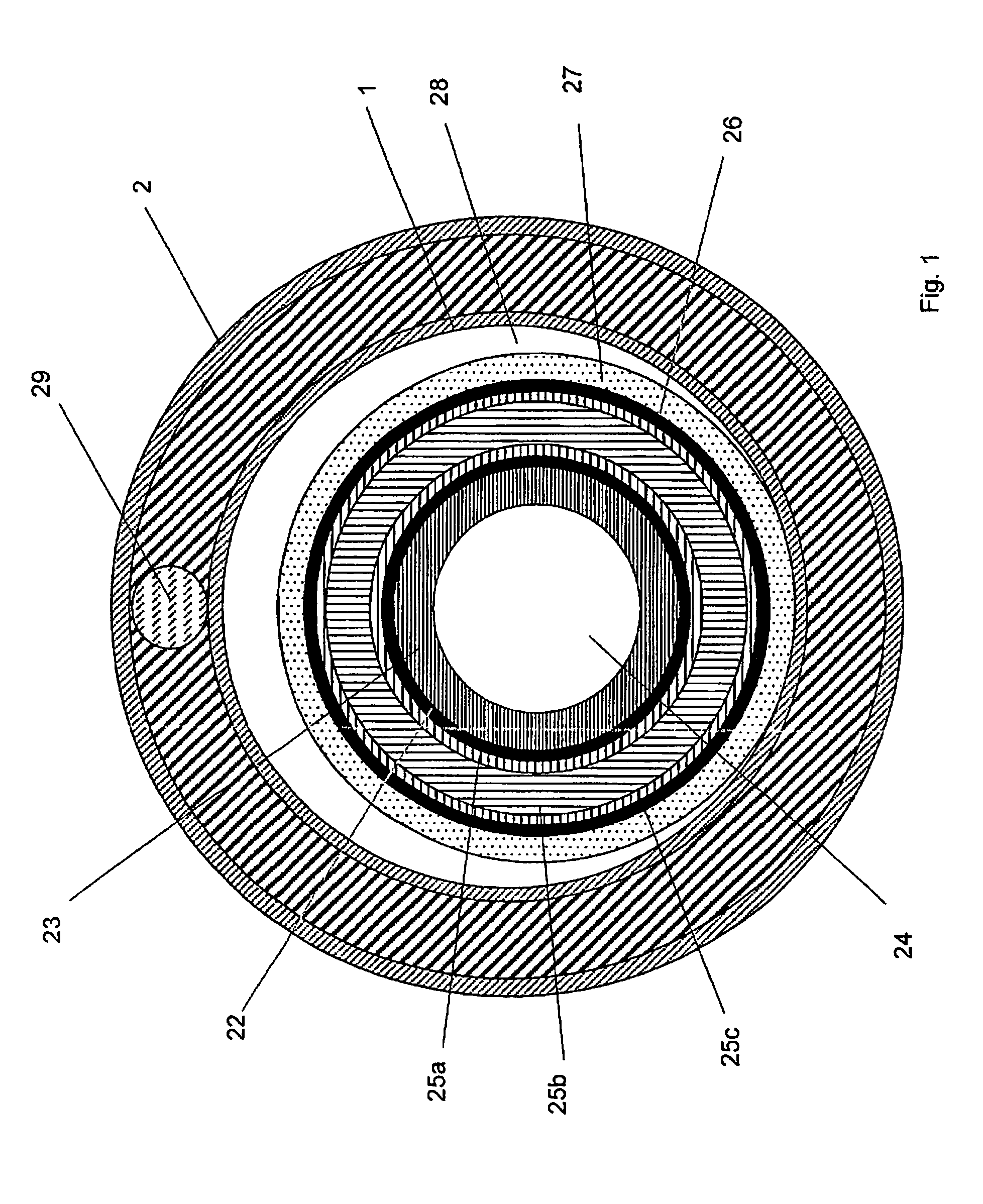
[0046]A cold dielectric superconducting cable (FIG. 1) generally comprises one or more layers of superconducting material (22) forming the so-called phase conductor, placed on a former (23), generally tubular, delimiting a first cryogenic fluid flowing channel (24). External to said superconducting material a dielectric is provided, comprising an electrostatic shield (25a), electric insulating material (25b) and a second electrostatic shield (25c). Around said dielectric one or more layers of superconducting material (26) are placed to form the so-called return conductor. On its turn, said return conductor is covered by a coating (27) of material suitable to provide mechanical resistance and impermeability against the cryogenic fluid. The above said cable is contained in a channel (28) delimited by the cryostat as explained below.

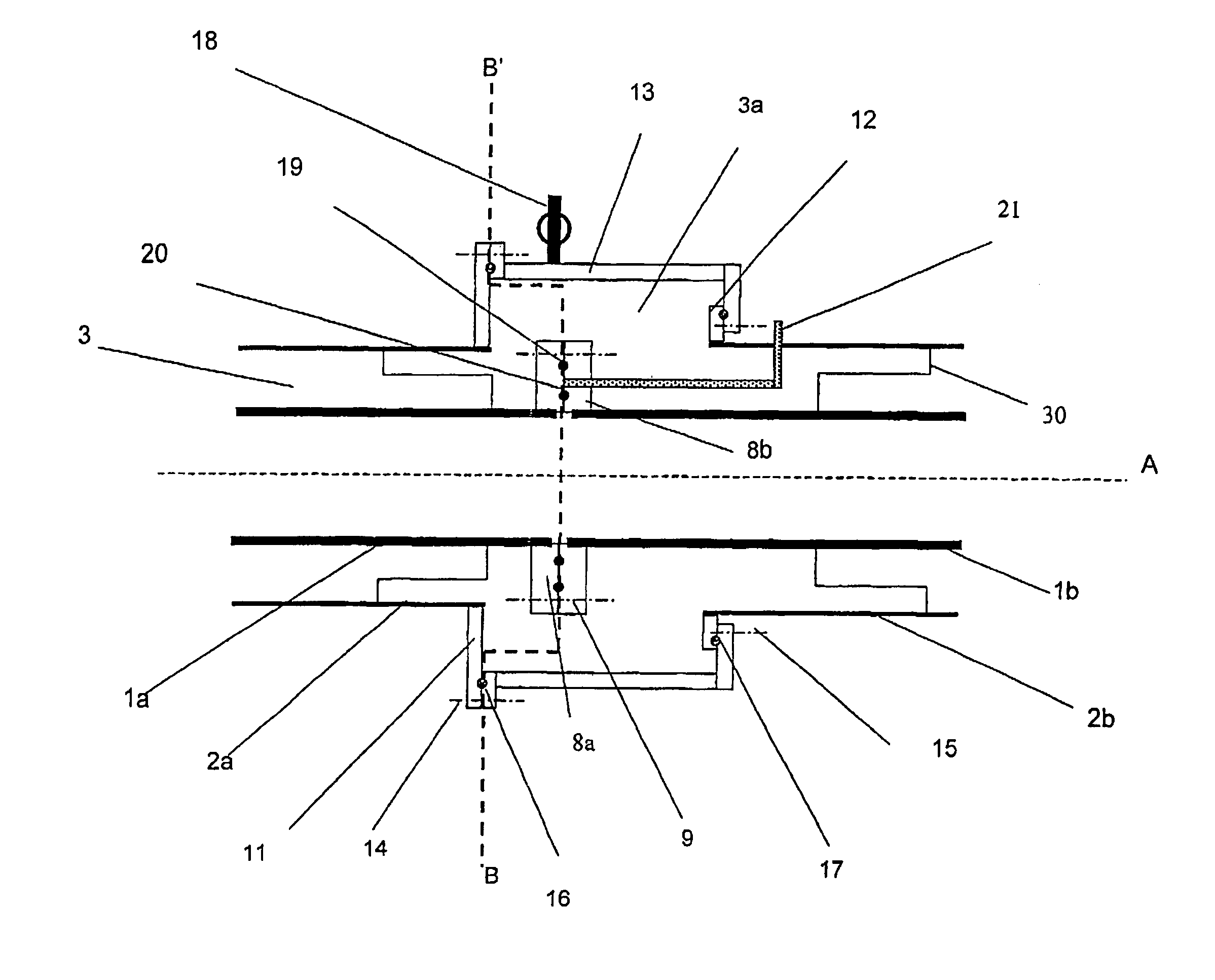
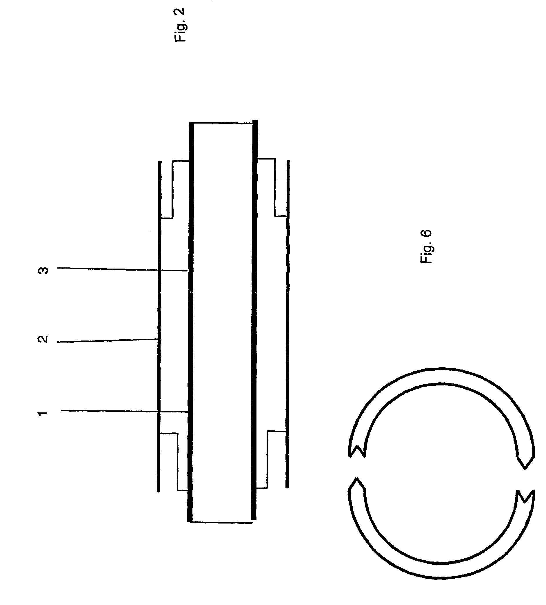
[0047]The wall externally circumscribing said channel (28) is formed by a cryostat comprising an inner tube (1) and an outer tube (2) delimiting an under v...


PUM

PropertyMeasurementUnit
diameteraaaaaaaaaa
diameteraaaaaaaaaa
Tcaaaaaaaaaa

Abstract

Electric power transport system having a cold dielectric superconducting cable, a cryostat and a cryogenic fluid. The cryostat has modules including an inner tube, an outer tube, a couple of gaskets, and a duct connected to the coupling surface between the gaskets of at least one flange with the environment external to the cryostat.

Description

CROSS REFERENCE TO RELATED APPLICATION[0001]This application is a national phase application based on PCT / IB01 / 02501, filed Dec. 17, 2001, the content of which is incorporated herein by reference.BACKGROUND OF THE INVENTION[0002]1. Field of the Invention[0003]The present invention relates to an electric power transport system comprising a cold dielectric superconducting cable.[0004]2. Description of the Related Art[0005]The term “superconducting cable” denotes a cable for transmitting current in conditions of so-called superconductivity, i.e. in conditions of almost null electric resistance. See, for example, Engelhardt J. S. et al., Application Consideration for HTSC Power Transmission Cable, 5th Annual Conference on Superconductivity and Application, Buffalo, N.Y., Sep. 24-26, 1991. In particular, the term “cold dielectric superconducting cable” indicates a cable showing two concentric phases (conductor and return) in superconducting material, electrically isolated one from the ot...

Claims


Application Information

Patent Timeline
Patent Type & Authority Patents(United States)
IPC IPC(8): H01B12/00H01R4/68H02G15/34H01B12/16
CPCH01B12/16H02G15/34Y02E40/647Y02E40/648Y02E40/60
Inventor LADIE', PIERLUIGICASTIGLIONI, VALTERNASSI, MARCO
Owner PRYSMIAN CAVI E SISTEMI ENERGIA
Why Eureka
Try Eureka