Lighting device and light source device
a technology of light source and light support device, which is applied in the direction of semiconductor devices for light sources, lighting and heating apparatus, and light support devices, etc., can solve the problem of small light distribution angle, and achieve the effect of excellent light distribution characteristics and simple configuration
- Summary
- Abstract
- Description
- Claims
- Application Information
AI Technical Summary
Benefits of technology
Problems solved by technology
Method used
Image
Examples
embodiment 1
[0053]One embodiment of the present invention is described below with reference to drawings.
1-1: Configuration of LED Bulb
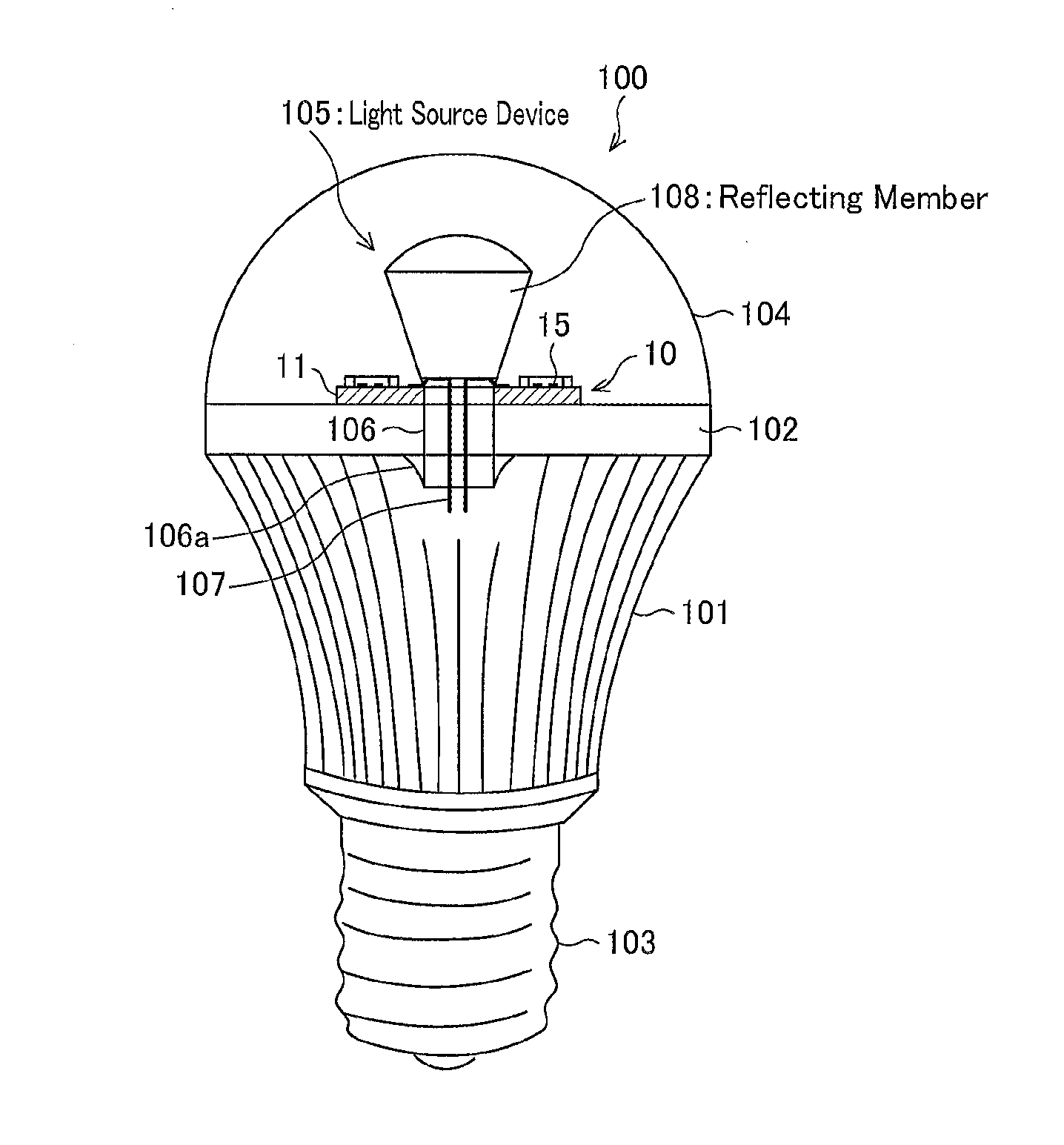
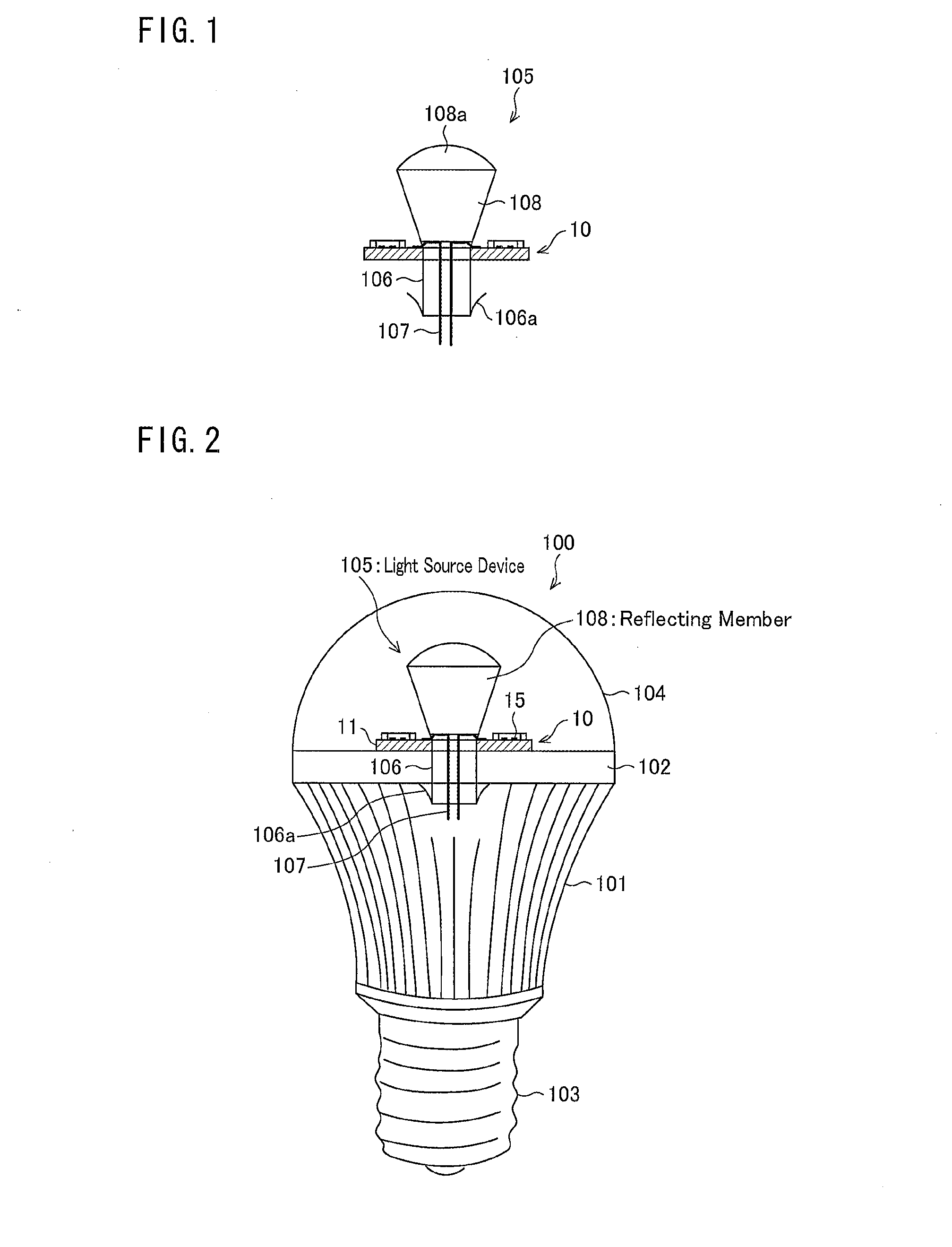
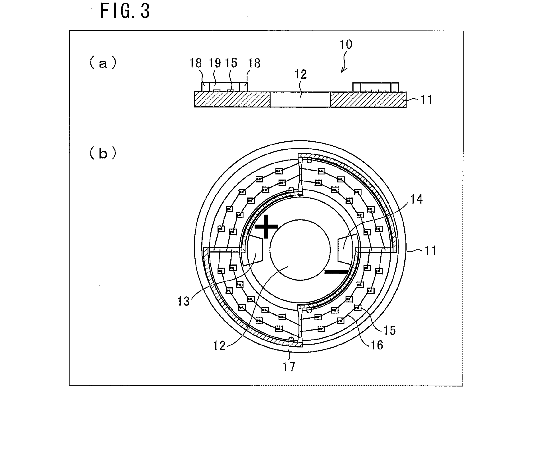
[0054]FIG. 2 is a view schematically showing one example of a configuration of an LED bulb 100 of the present embodiment. As shown in FIG. 2, the LED bulb 100 includes a housing 101, a mounting plate 102 (mounting base), a base 103, a globe 104, and a light source device 105.
[0055]The housing 101 is in an inverted truncated cone shape. The housing 101 has the mounting plate 102 fixed on its upper surface side, and the base 103 fixed on its lower surface side. The housing 101 contains, in its inside, a circuit substrate (not shown) on which a drive circuit is formed.
[0056]The mounting plate 102 is formed in a circular shape in a planer view. The light source device 105 and the globe 104 are provided on one surface (mounting surface) of the mounting plate 102. A through hole is provided at the center of the mounting plate 102. The base 103 is, for example, type E (...
embodiment 2
2-1: Configuration of LED Bulb
[0087]FIG. 5 is a view schematically showing one exemplary configuration of an LED bulb 200 in accordance with the present embodiment. As shown in FIG. 5, the LED bulb 200 includes a housing 101, a mounting plate 102, a base 103, a globe 104, and a light source device 205. That is, the LED bulb 200 is configured to include, compared with the LED bulb 100 of Embodiment 1, the light source device 205 instead of the light source device 105.
[0088]The light source device 205 is a light-emitting device in which an LED is employed as a light source. The light source device 205 has a pipe 206 having a function like that of a rivet for installation. At one end of the pipe 206, a hook 206a having a hooking part is formed. The light source device 205 is fixed to the mounting plate 102 by causing the hook 206a to be hooked by the mounting plate 102 when the pipe 206 is inserted into a through hole of the mounting plate 102. This allows the light source device 205 t...
embodiment 3
3-1: Configuration of LED Bulb
[0119]FIG. 7 is a view schematically showing one exemplary configuration of an LED bulb 300 in accordance with the present embodiment. As shown in FIG. 7, the LED bulb 300 includes a housing 101, a mounting base 302, a base 103, a globe 304, and a light source device 105. In other words, the LED bulb 300 is configured to include, compared with the LED bulb 100 of Embodiment 1, the mounting base 302 and the globe 304 instead of the mounting plate 102 and the globe 104, respectively.
[0120]The mounting base 302 is in a truncated cone shape. The mounting base 302 is fixed to the housing 101 so that its lower surface faces an upper surface of the housing 101. The light source device 105 is provided on an upper surface 302a (mounting surface) of the mounting base 302. An outer surface (at least a side face 302b) of the mounting base 302 has a light reflecting function. Furthermore, the mounting base 302 functions as a heat radiator. The mounting base 302 is m...
PUM
 Abstract
Description
Claims
Application Information
 - R&D
- Intellectual Property
- Life Sciences
- Materials
- Tech Scout
- Unparalleled Data Quality
- Higher Quality Content
- 60% Fewer Hallucinations
Browse by: Latest US Patents, China's latest patents, Technical Efficacy Thesaurus, Application Domain, Technology Topic, Popular Technical Reports.
© 2025 PatSnap. All rights reserved.Legal|Privacy policy|Modern Slavery Act Transparency Statement|Sitemap|About US| Contact US: help@patsnap.com


