Lighting device, sign board, show case and security lighting
A technology for lighting devices and reflective parts, which is applied to lighting devices, lighting device parts, display cabinets, etc., can solve problems such as uneven light and glare, and achieve simple structure, low cost, and good light distribution characteristics. Effect
- Summary
- Abstract
- Description
- Claims
- Application Information
AI Technical Summary
Problems solved by technology
Method used
Image
Examples
Embodiment approach 1
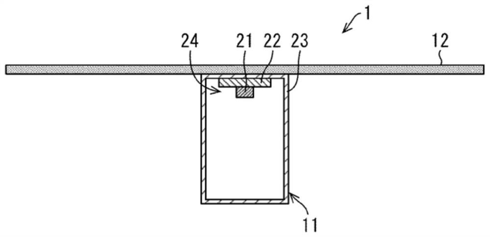
[0087] Embodiments of the present invention will be described below based on the drawings. figure 1 It is a longitudinal section showing the structure of the lighting device of this embodiment.
[0088] (Configuration of lighting device 1)
[0089] Such as figure 1 As shown, the lighting device 1 of the present embodiment includes a light emitting unit 11 and a reflector 12 . The light emitting part 11 includes LED21 which is a light source, the board|substrate 22 which mounts LED21, and the light source cover 23 which covers LED21.
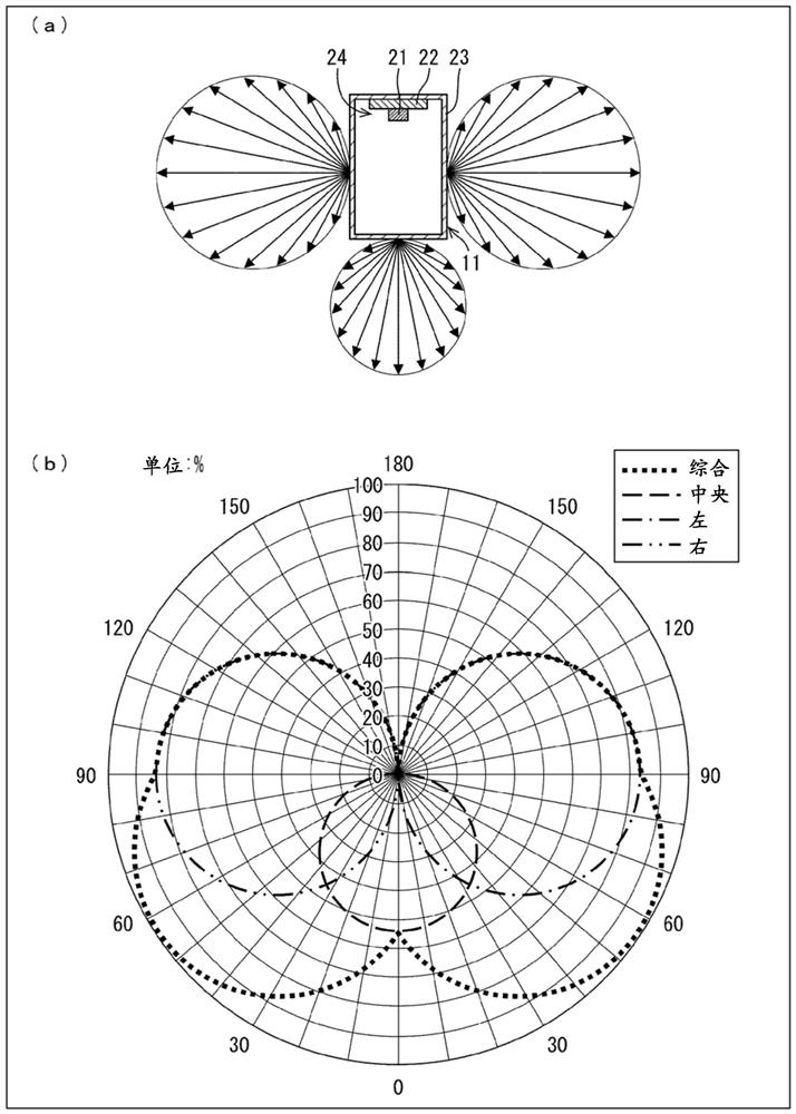
[0090] The light source cover 23 is milky white, for example, and has a long rectangle in the front direction of LED21 (the direction in which the light distribution of LED21 is strongest). Therefore, the light emitting unit 11 becomes a three-sided light emitting device that emits light on the front and left and right sides. The material of the light source cover 23 is, for example, Teijin Co., Ltd.
[0091] Co., Ltd.) MKL-3500ZAL. This ...
Embodiment approach 2
[0106] Other embodiments of the present invention will be described below based on the drawings. In addition, for convenience of description, the same reference numerals are assigned to components having the same functions as those described in the above-mentioned embodiment, and the description thereof will not be repeated.
[0107] (Configuration of lighting device 2)
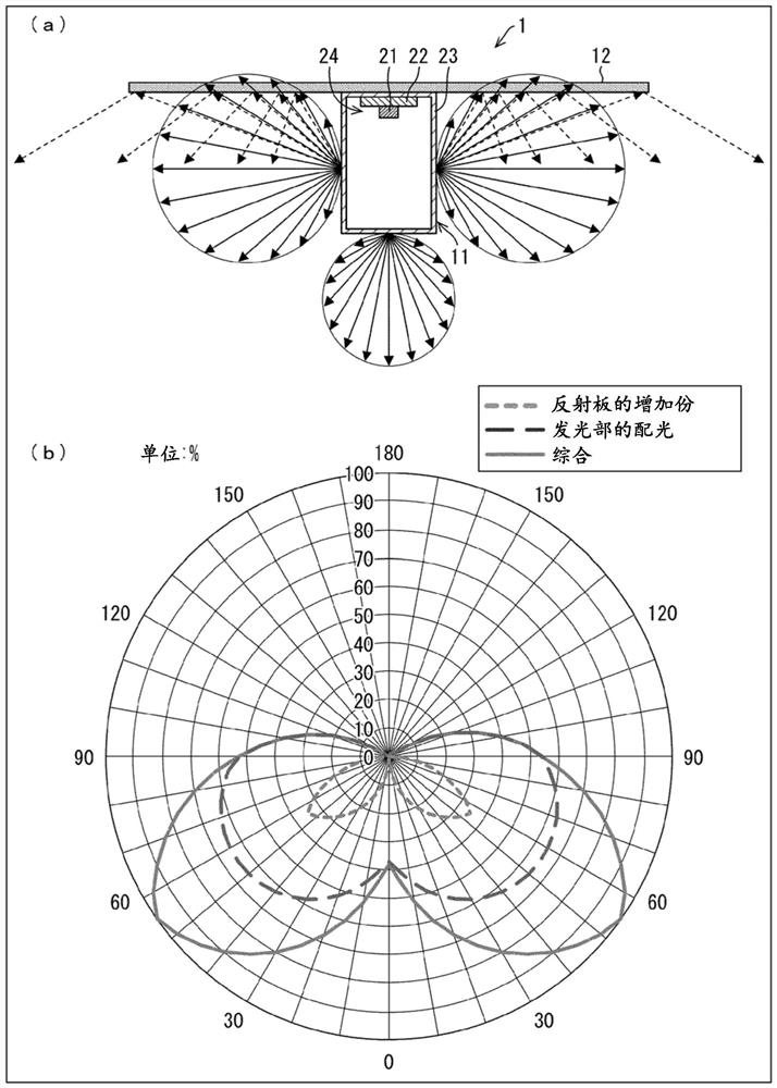
[0108] Other embodiments of the present invention will be described below based on the drawings. Figure 7 (a) is an explanatory diagram showing the configuration and light distribution state of the lighting device 2 according to the present embodiment, Figure 7 (b) means Figure 7 The graph of the light distribution characteristic of the illuminating device 2 shown in (a). in addition, Figure 7 (a) shows the configuration of the lighting device 2 in a longitudinal section.
[0109] The lighting device 2 of this embodiment is as Figure 7 As shown in (a), a reflector 41 is included instead of the refl...
Embodiment approach 3
[0119] Another embodiment of the present invention will be described below based on the drawings. In addition, for convenience of description, the same reference numerals are assigned to components having the same functions as those described in the above-mentioned embodiment, and the description thereof will not be repeated.
[0120] (Structure of Kanban 51)
[0121] Here, a configuration example of a signboard including the lighting device of the present embodiment will be described. Figure 10 (a) is contained within Figure 9 A perspective view of the kanban of the lighting device 32 shown, Figure 10 (b) is a longitudinal sectional view showing the installed state of the lighting device of the signboard 51, Figure 10 (c) is Figure 10 Illumination distribution diagram (in lux) of the kanban shown in (a).
[0122] Such as Figure 10 As shown in (a), the kanban 51 includes a rectangular parallelepiped box-shaped box 52 . Although the up and down direction of the kan...
PUM
 Abstract
Description
Claims
Application Information
 - R&D
- Intellectual Property
- Life Sciences
- Materials
- Tech Scout
- Unparalleled Data Quality
- Higher Quality Content
- 60% Fewer Hallucinations
Browse by: Latest US Patents, China's latest patents, Technical Efficacy Thesaurus, Application Domain, Technology Topic, Popular Technical Reports.
© 2025 PatSnap. All rights reserved.Legal|Privacy policy|Modern Slavery Act Transparency Statement|Sitemap|About US| Contact US: help@patsnap.com


