
Communication apparatus, communication system, and communication method

Inactive Publication Date: 2015-05-21
TOYOTA JIDOSHA KK
View PDF4 Cites 0 Cited by
  • Summary
  • Abstract
  • Description
  • Claims
  • Application Information

AI Technical Summary

Benefits of technology

The present invention aims to improve the reliability of communicated messages by preventing unauthorized communication. This is achieved by providing a communication system and method that uses a unique identifier and a simulated identifier that are continuous. This design ensures that the priority of the selected simulated identifier remains the same as the unique identifier, while also allowing for application while maintaining the priority. The technical effect of this invention is improved reliability of communicated messages.

Problems solved by technology

However, the unauthorized and changed communication terminal can use the converted unique information acquired from the message transmitted through the network until the network unique value is updated.
Thus, the communication system may not be able to prevent unauthorized communication with the unauthorized and changed communication terminal when using the converted unique information acquired from the message flowing through the network.

Method used


Image

  • Communication apparatus, communication system, and communication method
  • Communication apparatus, communication system, and communication method
  • Communication apparatus, communication system, and communication method

Examples


Embodiment Construction

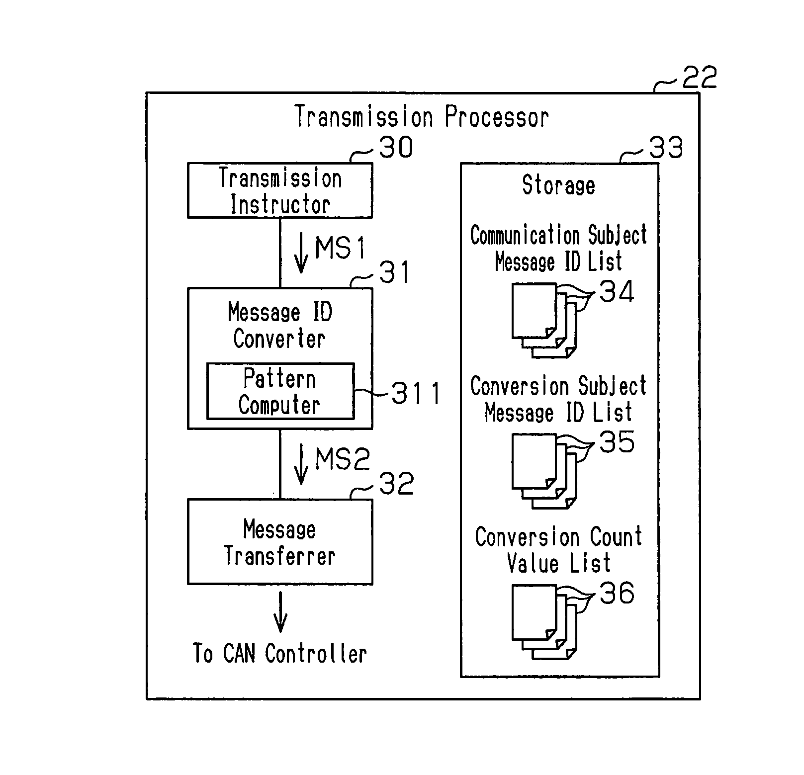
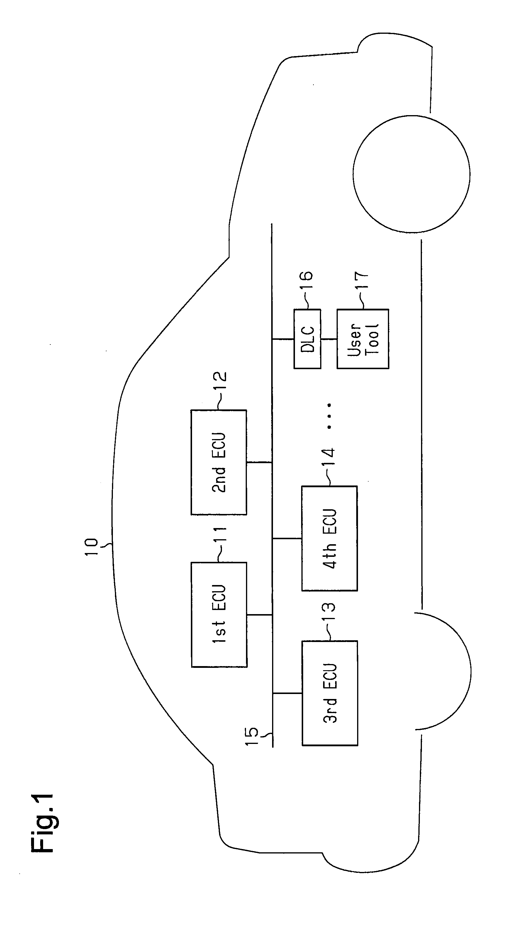
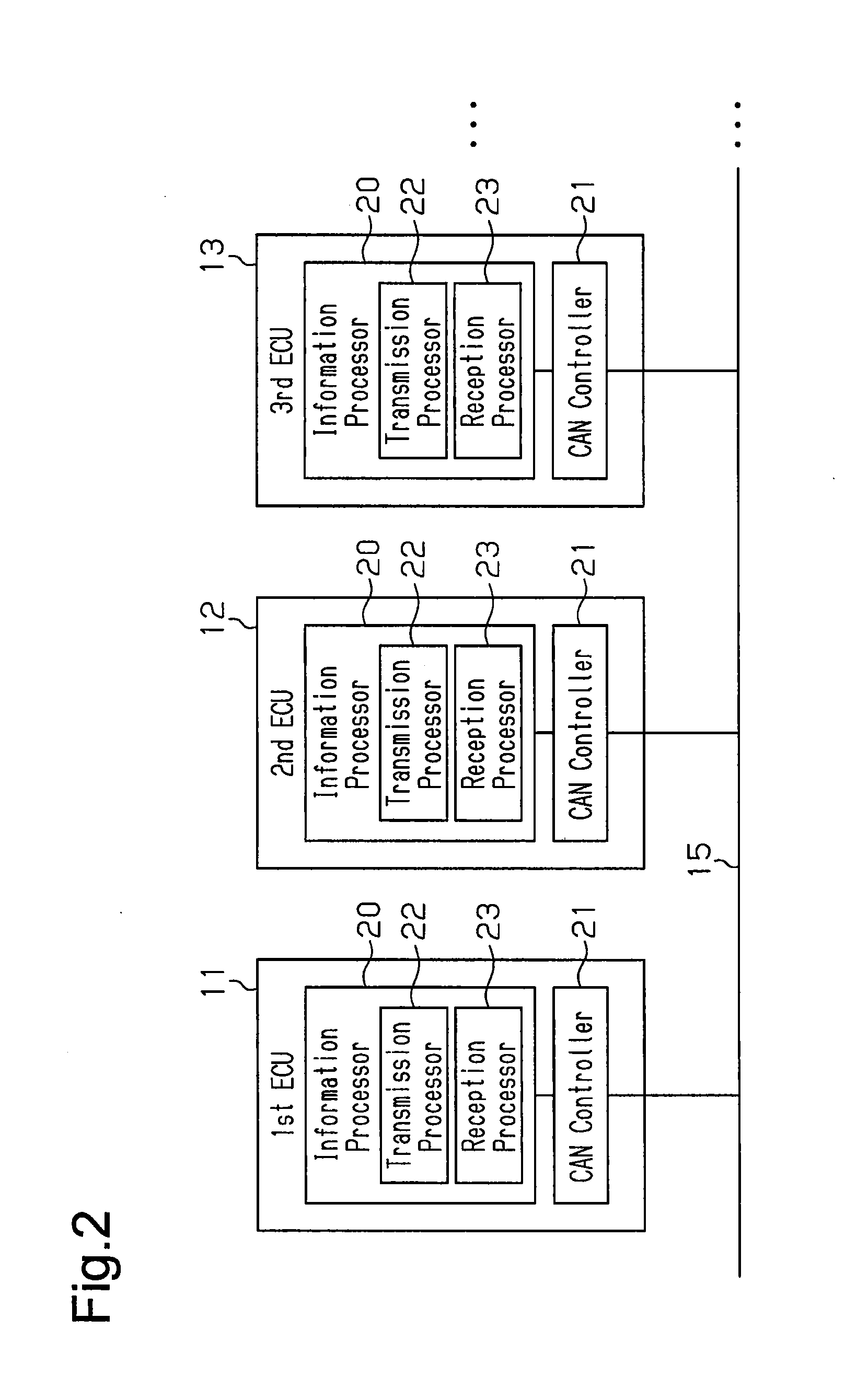
[0046]A communication system according to a first embodiment of the present invention will now be described with reference to FIGS. 1 to 10.

[0047]As shown in FIG. 1, a vehicle 10 includes an in-vehicle network system serving as a communication system. The in-vehicle network system includes first to fourth electronic control units (ECU) 11 to 14 serving as communication apparatuses, and a communication bus 15 to which the first to fourth ECUs 11 to 14 are connected. The first to fourth ECUs 11 to 14 are thus able to exchange (transmit and receive) various types of information used for control or the like with one another through the communication bus 15. The in-vehicle network system is configured as a CAN network to which the CAN (Controller Area Network) protocol is applied as the communication protocol. The communication bus 15 is, for example, a twist pair cable. A further ECU can thus be easily added to the communication bus 15 so that the added ECU can easily transmit and recei...


PUM


Abstract

Provided is a communication system that can aim to prevent unauthorized communications, i.e., to improve the reliability of communicated messages. A communication system comprises a plurality of ECUs connected to a communication line such that the plurality of ECUs can communicate communication messages. Each of the plurality of ECUs has a unique ID and also has a plurality of dummy IDs defined, as substitute candidates, from the unique ID. The ECU further has a defined pattern in which to cause one of the plurality of dummy IDs to be selected as a dummy ID that is a substitution object to be converted to the unique ID. Among the plurality of ECUs, the selection conditions of the substitution objects based on the pattern are synchronized, and the unique ID, which has been added to a communication message, is converted to a dummy ID on the basis of the pattern. Further, among the plurality of ECUs, the communication message, to which the dummy ID after the conversion has been added, is transmitted, and the dummy ID, which is acquired from the received communication message, is reconverted to the unique ID on the basis of the pattern. Finally, among the plurality of ECUs, the received communication message is identified on the basis of the unique ID after the reconversion.

Description

TECHNICAL FIELD[0001]The present invention relates to a communication apparatus that is network-connected in a vehicle or the like, a communication system in which a plurality of communication apparatuses are network-connected, and a communication method.BACKGROUND ART[0002]As known in the art, a plurality of electronic control units (ECU) mounted on a vehicle often configure a communication system in which each of the electronic control units is network-connected to each other so that information (vehicle information) of the electronic control units can be communicated between the electronic control units. In other words, such a communication system is configured as a vehicle network system with the ECUs serving as communication apparatuses. Such a vehicle network systems is a controller area network (CAN).[0003]The CAN enables each ECU, which shares a bus or a communication line, to determine to send a message on a bus, and hence a message is easily transmitted from each ECU to th...

Claims


Application Information

Patent Timeline
IPC IPC(8): G06F13/42G06F13/26
CPCG06F13/26G06F13/423H04L12/40169H04L2012/40215H04L2012/40273H04L61/2539H04L12/40032H04L63/123H04L67/12
Inventor SHIRAI, KUNIYOSHI
Owner TOYOTA JIDOSHA KK
Learn More