
Method of manufacturing fluttering robot using a fluid-structure interactive numerical model for developing controls for wing driving apparatus

Inactive Publication Date: 2009-09-01
SHARP KK
View PDF7 Cites 0 Cited by
  • Summary
  • Abstract
  • Description
  • Claims
  • Application Information

AI Technical Summary

Benefits of technology

[0038]According to this method, the fluid-structure interactive analysis used for analyzing behavior of a structure other than the living organism is applied to analysis of behavior when a structure as a living organism performs a prescribed motion in a fluid, whereby it becomes possible to prepare the fluid-structure interactive numerical model including interaction between the behavior of the fluid and the behavior of the structure as the living organism.
[0089]As a result, it becomes possible to determine the method of controlling wing driving apparatus for driving artificial wings such that even the artificial wings of the fluttering robot assume the manner of fluttering flight that is close to the actual manner of fluttering flight of a structure represented by the equivalent numerical model of actual structure, that is, the actual structure of an insect.

Problems solved by technology

The reason for this is that there is an almost infinite combinations of the manner of fluttering and the wing shapes of insects, and hence a formidable time is necessary to optimize the manner of fluttering or the wing shape of the insect, to meet a requested specification of the fluttering flight, and hence such an approach is impractical.
In the above described method, however, it is impossible to simultaneously obtain the behavior of the air as the fluid and the behavior of the insect as a structure of a living organism.
Therefore, it has been impossible to prepare a numerical model that involves interaction between the air and the wing of the insect, that is, to prepare a fluid-structure interactive numerical model.
Though it is possible by this method to grasp the wing behavior, it is not at all possible to grasp fluid behavior.
What is obtained by this method, however, is the shape of the fluid flux of the trace and not the velocity of the flowing trace.
Therefore, it has been unsuccessful to obtain numerical model of the fluid behavior.
It is noted, however, that only extremely small particles can float and not fall down, over a long period of time in a fluid having very small density such as air.
Therefore, considering the capability of identification by a camera, it is impossible to use this method when the fluid is air.
When an object moving with to period of about 30 Hz is to be captured with high accuracy as video images, the number of frames as high as 1024 is still insufficient.
In order to capture to movement of a particle of 3 μm as video images, it follows that the product of CCD camera sensitivity and the luminance of illumination must be multiplied 10000 times. Therefore, such a method is considered impractical.
Therefore, by this method, it is impossible to correctly grasp deformation of particle structure moving in the fluid.
As described above, it has been unsuccessful through conventional methods to prepare an interactive numerical model between fluid and structure.
For example, it has been impossible to properly represent a movement of a petal when a butterfly rests on a flower.
By any of the above described methods, it has been impossible to calculate torque for driving the wing, for example, for a fluttering robot that mimics motion of a wing of an insect, since in methods (1) and (2), actual measurement of physical parameters is impossible and in method (3), force used for deformation of the wing is not considered as the wing deformation is different from the actual structure.
Therefore, it has been difficult to obtain numerical model of a driving force for driving the wing, which is most important in forming a control mechanism controlling the fluttering flight.
In short, by the numerical models prepared in accordance with the prior art, it has been difficult to obtain numerical expression of motion of a structure, which is a living organism, in a fluid, including fluid-structure interaction.
Further, when a robot mimicking the structure as a living organism is to be manufactured, it has been necessary to design the driving force, allowing for a margin of the driving force, as it has been difficult to calculate the numerical model of driving force for driving the structure as a living organism.
By any of the conventional methods, it is impossible to prepare a numerical model of the manner of fluttering flight of the robot mentioned above.
Therefore, such a study can be made only under very limited conditions.
Therefore, either by the method using a numerical model or by the method through experiment, it has been difficult to efficiently find the manner of fluttering drive of a fluttering robot.

Method used


Image

  • Method of manufacturing fluttering robot using a fluid-structure interactive numerical model for developing controls for wing driving apparatus
  • Method of manufacturing fluttering robot using a fluid-structure interactive numerical model for developing controls for wing driving apparatus
  • Method of manufacturing fluttering robot using a fluid-structure interactive numerical model for developing controls for wing driving apparatus

Examples


first embodiment

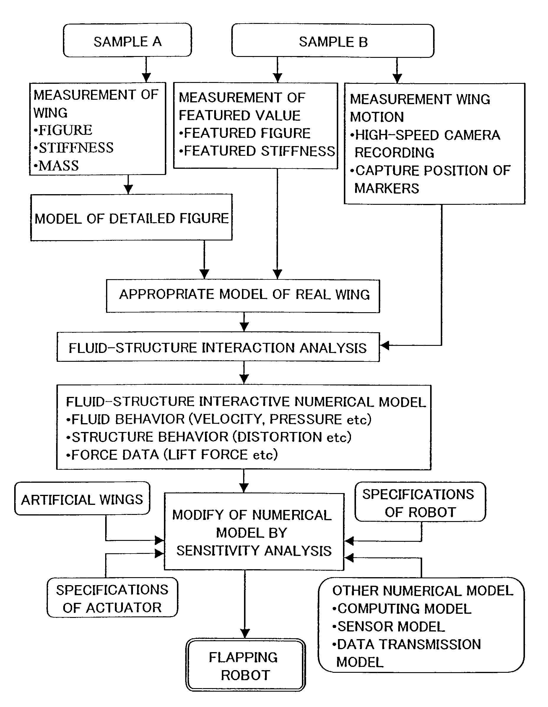
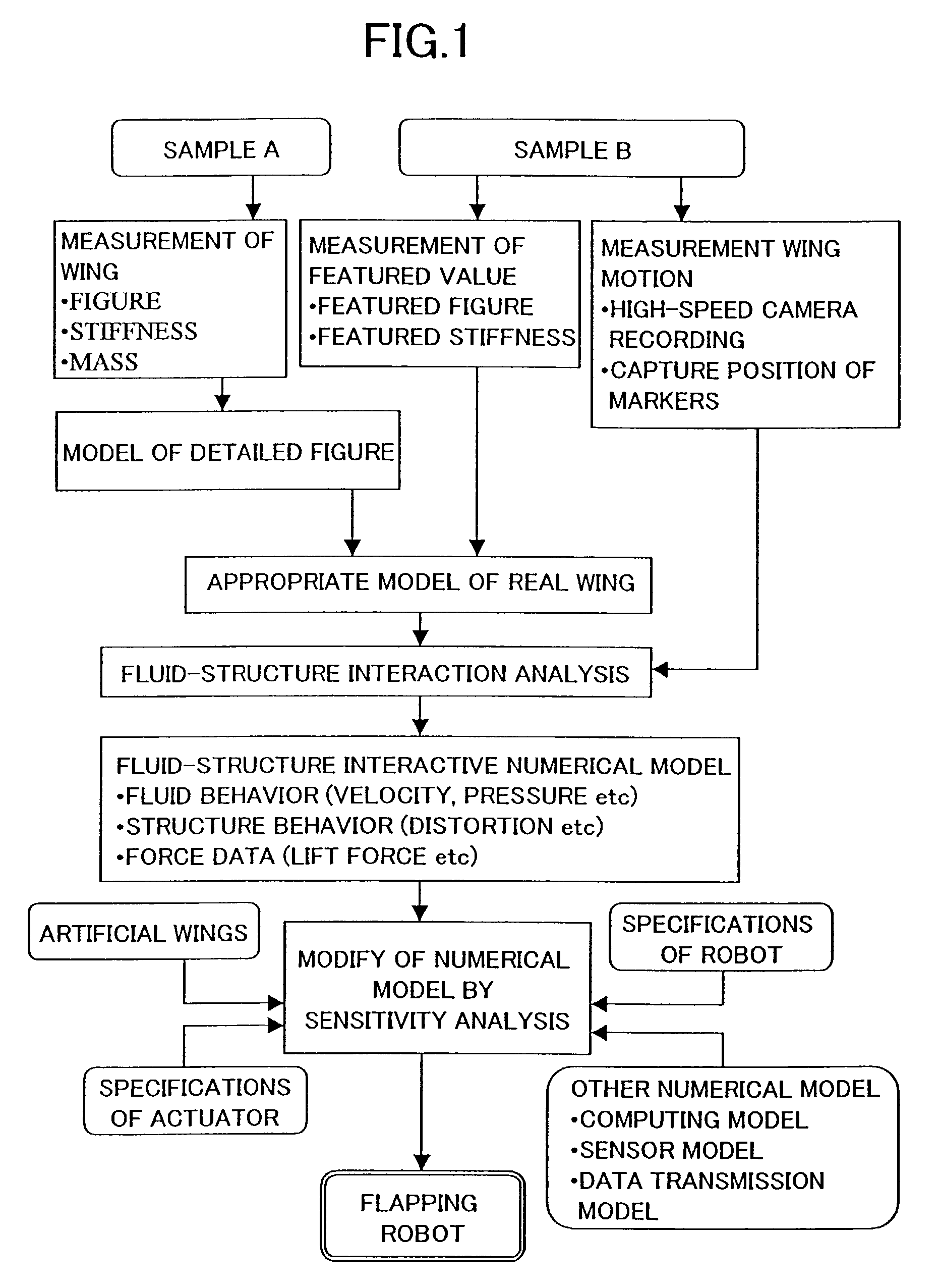
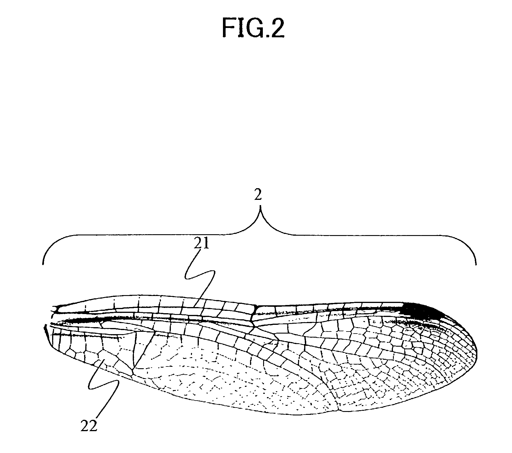
[0112]First, referring to Tables 1 to 6 and FIGS. 1 to 20, the method of preparing fluid-structure interactive numerical model in accordance with the first embodiment and the method of manufacturing a fluttering robot using the same will be described.

[0113]The method of preparing fluid-structure interactive numerical model of the present embodiment is to prepare a numerical model related to air as the fluid and a numerical value related to the wing structure, obtained by analyzing structure of the wing of an insect and the manner of fluttering flight of the insect, when the insect flies fluttering in the air.

[0114]The method of manufacturing a fluttering robot in accordance with the present embodiment is to manufacture a fluttering robot mimicking the structure of the wings of an insect and mimicking the manner of fluttering flight of the insect, using a numerical model prepared by the method of preparing fluid-structure interactive numerical model described above.

[0115]Specifically...

second embodiment

[0317]The method of preparing the fluid-structure interactive numerical model in accordance with the second embodiment will be described with reference to Table 7 and FIGS. 21 to 26.

[0318]The numerical model of the structure used in the method of preparing fluid-structure interactive numerical model of the present embodiment corresponds to the numerical model of the structure used in the method of preparing fluid-structure interactive numerical model of the first embodiment shown in FIG. 4, with the thicknesses of the wing changed, from 0.35 mm, 0.18 mm, 0.15 mm, 0.12 mm, 0.1 mm and 0.05 mm, respectively, to 0.045 mm, 0.012 mm, 0.010 mm, 0.008 mm, 0.006 mm and 0.004 mm.

[0319]In the method of preparing fluid-structure interactive numerical model of the first embodiment, the fluttering motion is approximately in the vertical direction, and hence the direction of generation of the lift force is positive along the y axis in FIG. 17. In the method of preparing fluid-structure interactive...


PUM


Abstract

A numerical model related to fluttering of an insect, when an equivalent model of actual structure of a wing of the insect is moved in the air in accordance with a model of fluttering motion of the wing of the insect is calculated by fluid-structure interactive analysis, in which behavior of the wing and behavior of the air are given as numerical values, including interaction therebetween. Thereafter, a method of controlling a fluttering robot, wing shape and the like are determined by modifying numerical models of fluttering of an insect prepared by fluid-structure interactive analysis, in accordance with sensitivity analysis. Accordingly, a method of preparing numerical models of wing and air considering the behavior of the wing of the insect in the air is provided and, in addition, a method of manufacturing a fluttering robot utilizing the numerical model prepared by this method of preparing numerical model can be provided.

Description

[0001]This application is a continuation-in-part of U.S. application Ser. No. 10 / 269,181, filed Oct. 11, 2002 now abandoned, the teachings of which are incorporated herein by reference.BACKGROUND OF THE INVENTION[0002]1. Field of the Invention[0003]The present invention relates to a method of preparing a fluid-structure interactive numerical model for preparing a numerical model related to a fluid and a numerical model related to a structure when an actual structure as a living organism performs a prescribed motion in the fluid, as well as to a method of manufacturing a fluttering robot using the same.[0004]2. Description of the Background Art[0005]Conventionally, attempts have been made to prepare a numerical model of the manner of fluttering flight that mimics the flight of an insect as an example of a structure of a living organism, with the manner of flight given as numerical expression, by a computer. Further, a simulator or a game of fluttering flight has been known that utili...

Claims


Application Information

Patent Timeline
IPC IPC(8): G06G7/60G05B13/04G05B19/18G06G7/72G09B9/05G09B9/10G01M9/08A61B5/103B64C33/02G06F17/50G06F19/00G06G7/48
CPCG06F17/5018G06F2217/16G06F2217/12G06F30/23G06F2119/18G06F2111/10
Inventor HAMAMOTO, MASAKIOHTA, YOSHIJIHARA, KEITAHISADA, TOSHIAKI
Owner SHARP KK
Learn More