
Injector for the injection of a fluid and method for the control of an injector

a technology of injector and injector, which is applied in the direction of flow monitors, medical devices, diagnostics, etc., can solve the problems of complete turning off unnecessary power reduction of the drive power of the drive mechanism, and interruption of the injection process

Active Publication Date: 2015-06-04
ULRIKH GMBKH & KO KG
View PDF2 Cites 3 Cited by
  • Summary
  • Abstract
  • Description
  • Claims
  • Application Information

AI Technical Summary

Benefits of technology

This patent is about a method for controlling an injector to prevent pressure hazards and avoid unnecessary prolongations of the injection process. The method uses a control device that compares the recorded pressure of the fluid to a theoretical pressure and reduces the power of the pump when the actual pressure exceeds the theoretical pressure. This prevents the actual pressure from being above the theoretical pressure for a longer period of time and avoids the need for unnecessary switching off of the pump or power reduction of the drive mechanism. This method allows for an increase in efficiency and throughput of multiple injection processes without compromising patient safety.

Problems solved by technology

This known injection system and the method for its control prove to be disadvantageous, however, because brief rises of the fluid pressure, which may appear, for example, with the start of the injection system at the beginning of the injection process, can lead to an unnecessary power reduction of the drive power of the drive mechanism, or with very high, brief pressure peaks, can even lead to a complete turning off of the drive mechanism and thus to an interruption of the injection process.
This leads to a prolongation of the injection time, in which the patient is to be supplied with a prespecified quantity (dosage) of the fluid to be injected.
With an interruption of the injection process, a testing of the system by the operator and a restart of the injection process are necessary, which likewise leads to an undesired prolongation of the time of the injection process and to a reduction of the throughput with a number of injection processes that are to be carried out with the injection system, one after the other.

Method used


Image

  • Injector for the injection of a fluid and method for the control of an injector
  • Injector for the injection of a fluid and method for the control of an injector
  • Injector for the injection of a fluid and method for the control of an injector

Examples


Embodiment Construction

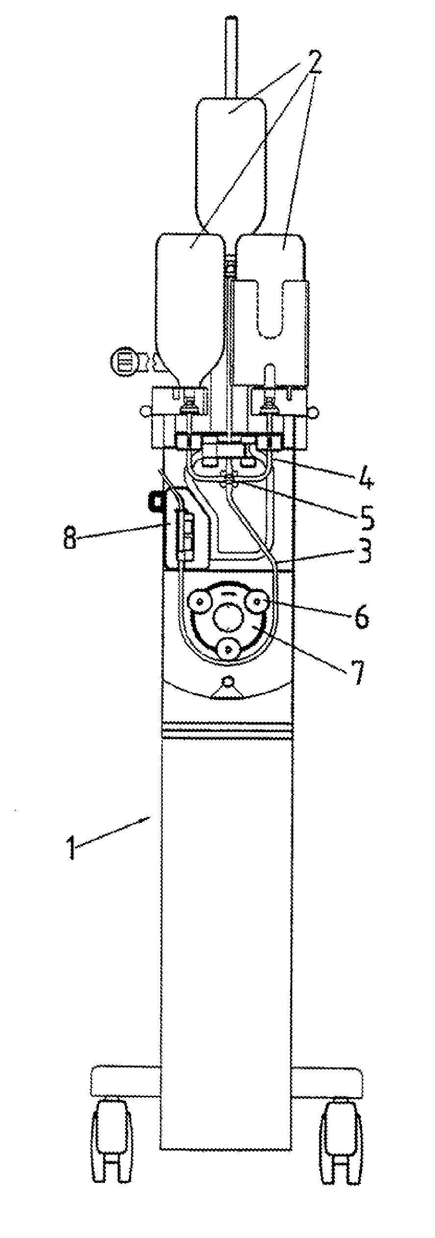
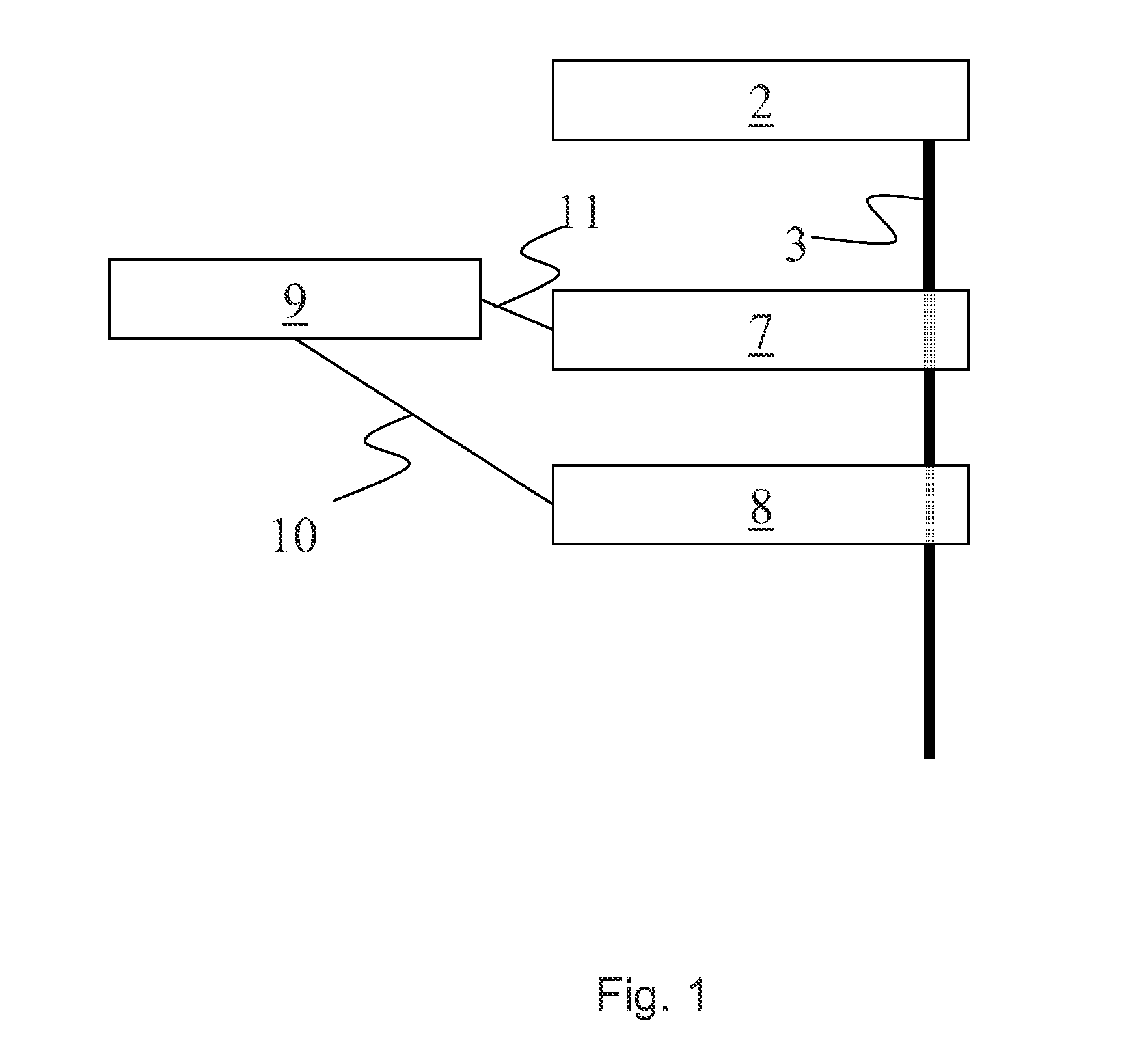
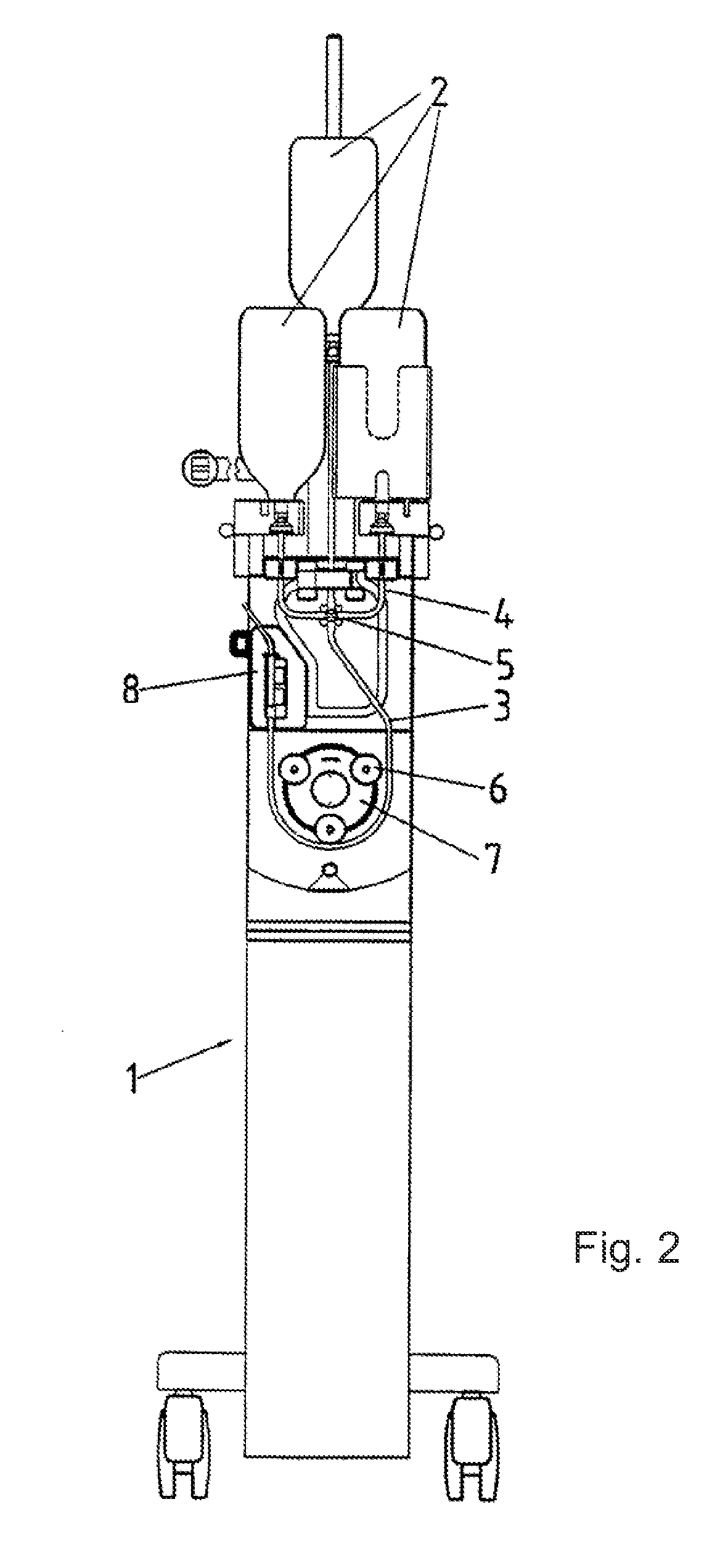
[0018]In FIG. 1, the components of an injector in accordance with the disclosure are schematically shown in a block diagram. The injector 1 can be used, for example, for the injection of a fluid, in particular, a liquid contrast agent for X-ray or magnetic resonance image-assisted investigations in human or animal bodies. The injection of the fluid to be injected thereby takes place intravenously, as a rule. The fluid to be injected is kept in a fluid reservoir 2. An injection hose 3 is connected to the fluid reservoir 2. The injection hose 3 is coupled with a pump 7. Via the pump 7, the fluid stored in the fluid reservoir 2 is conveyed through the injection hose 3. Preferably, the pump 7 is a hose pump into which the injection hose 3 is placed, so that the hose pump can convey the fluid from the fluid reservoir 2 through the injection hose 3. In this way, it is ensured that the pump does not come into contact with the fluid to be conveyed, which guarantees the sterility of the inje...


PUM


Abstract

An injector for the injection of a fluid into human or animal bodies with a pump for the conveying of the fluid at a flow rate, and with a control device for the control of the pump and for the setting of a desired flow rate (theoretical flow) of the fluid, and a pressure measurement device coupled with the control device for the recording of the pressure of the fluid conveyed by the pump, wherein a theoretical pressure is specified for the control device. In order, on the one hand, to reliably prevent an exceeding of a pressure hazard in the injection system and, on the other hand, to avoid an unnecessary prolongation of the injection process by a power reduction or a switching off of the drive mechanism, and to increase the throughput of several injection processes carried out with the injector one after the other, provision is made so that the control device compares the pressure of the fluid recorded by the pressure measurement device to the theoretical pressure, and when the theoretical pressure is exceeded over a time period, integrates the chronological pressure course of the pressure recorded by the pressure device over this time period for the determination of a pressure integral, and switches off the pump or operates it with a lower pump power if the determined pressure integral exceeds a prespecified integral limiting value.

Description

FIELD OF THE DISCLOSURE[0001]The disclosure concerns an injector and a method for the control of an injector.BACKGROUND OF THE DISCLOSURE[0002]From U.S. Pat. No. 6,673,033 B1, injector systems for the injection of a fluid in medicinal injection methods and a method for their control are known, wherein the injector system has a drive mechanism with which a fluid to be injected is placed under pressure and a sensor to record a variable that is proportional to the fluid pressure and comprises a pressure monitoring mechanism, which is connected with the sensor and the drive mechanism and interrupts the injection process if the sensor measures a value of the recorded variable that corresponds to a pressure hazard (pressure hazard limit). In order to prevent the fluid pressure from approaching the pressure hazard limit or from exceeding it, provision is also made in the pressure monitoring mechanism so that the drive output of the drive unit is limited to a prespecified limiting value if ...

Claims


Application Information

Patent Timeline
Patent Type & Authority Applications(United States)
IPC IPC(8): A61M5/00A61M5/142A61M5/172A61M5/168
CPCA61M5/007A61M5/16854A61M2205/3331A61M5/16804A61M5/172A61M5/14212A61M5/14228A61M5/142A61M5/168A61M5/48Y10S128/12
Inventor SEIBOLD, FELIX
Owner ULRIKH GMBKH & KO KG
Learn More