Surface machining apparatus

a surface machining and apparatus technology, applied in the direction of turning apparatus, feeding apparatus, automatic control device, etc., can solve the problems of affecting the safety of operators, affecting the axial movement of tools, and damage to the spigot and the machin

Inactive Publication Date: 2015-06-04
FURMANITE AUSTRALIA
View PDF26 Cites 7 Cited by
  • Summary
  • Abstract
  • Description
  • Claims
  • Application Information

AI Technical Summary

Benefits of technology

[0018]A particular advantage of wireless operation of the controller is that the operator can be located remotely of the apparatus, perhaps tens or even hundreds of metres depending on the range of the wireless receiver of the control module. A flange facing machine having a rotating arm can be hazardous to the operator and it is much preferred that the operator not be standing in close proximity while the machine is operational.
[0019]A further advantage of wireless operation is that the operator may reprogram the controller on the fly, rather than connecting and disconnecting a computer in order to issue different sets of instructions to the controller.

Problems solved by technology

Degradation of the flange surface on industrial flanges and vessel / reactor gasket surfaces can lead to leakage and so these flange surfaces or gasket faces can require resurfacing from time to time.
A known problem with existing portable flange facing machines is that axial movement of the tool post carrying the cutting tool towards or away from the spindle is achieved by mechanical means, for example by a control crank, as described in U.S. Pat. No. 5,630,346.
An additional problem with known machines is that, in order to move the cutting tool to set spigot positions or ‘V’ grooves, the operator must watch the cutting tool carefully and stop the machine at the correct instant.
If the operator is distracted, the cutting tool can dig into the spigot face, potentially causing damage to the spigot and to the machine.
A further problem with manual operation of known machines as described above is that the operator is required to be in close contact with the machine, posing a safety hazard to the operator.
A similar problem exists during boring operations using portable boring bars which are used for both refurbishment and new construction.
A mechanically driven facing arm (typically positioned at right angles to the axial line of the bore) and used to machine faces has the same mechanical complexity as described above, is typically limited to one feed rate per revolution of the bar and again there is difficulty in providing precise control regarding spigot face diameters and the like.

Method used


Image

  • Surface machining apparatus
  • Surface machining apparatus
  • Surface machining apparatus

Examples


Embodiment Construction

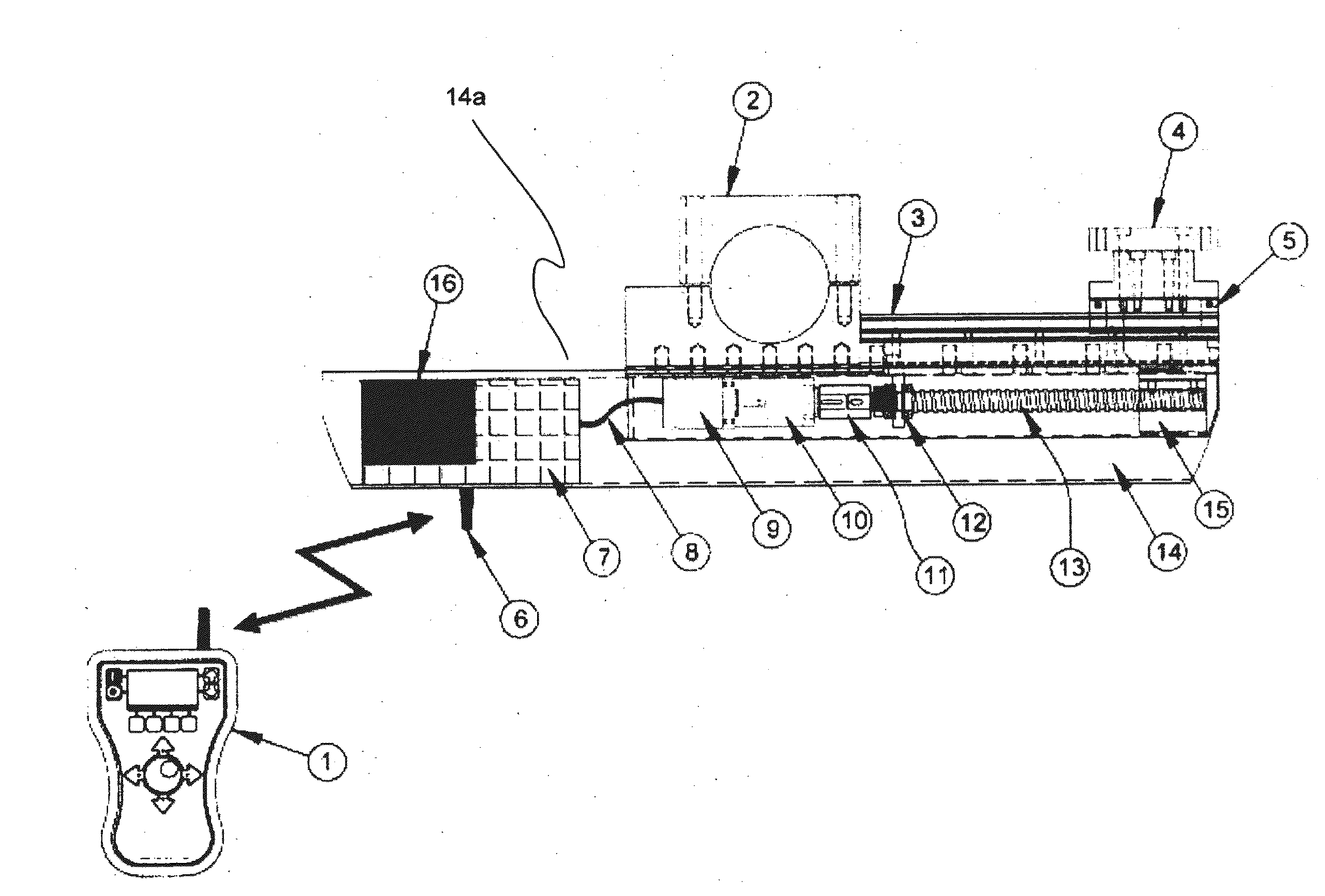
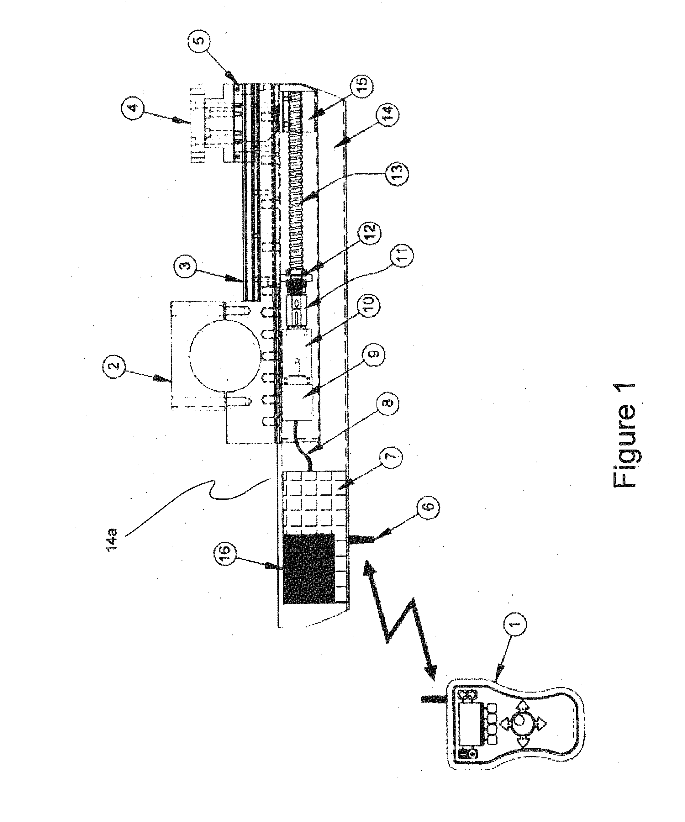
[0031]Referring initially to FIG. 1, there is shown a facing arm 14, including an arm casing 14a having an internal cavity which houses electrically powered drive means including feed motor 9, feed gearbox 10, drive coupling 11, thrust bearings 12 and lead screw 13. A battery 16 provides power to a control module 7, and to the feed motor 9.

[0032]The facing arm 14 includes a machining element in the form of a tool post 4 for receiving a cutting tool. The tool post 4 is mounted to a runner block 5 which is adapted to move along a linear rail 3 so as to position the tool post 4. The tool post 4 may alternatively move along a “Vee” bed (not shown).

[0033]Control module 7 is in communication with a wireless remote control module 1 via an RF antenna 6 mounted to the arm casing 14a. The wireless remote control module 1 may be a custom controller with circuitry for implementing a predetermined set of functions. In other embodiments, the controller 1 may include user-programmable circuitry. I...


PUM

PropertyMeasurementUnit
internal diameteraaaaaaaaaa
diametersaaaaaaaaaa
surface finishesaaaaaaaaaa

Abstract

A facing arm for machining a surface of a workpiece, including: a machining element which is movable along an axis of the facing arm thereby to position the machining element relative to the surface of the workpiece; and electrically powered drive means for moving the machining element along the axis of the facing arm.

Description

TECHNICAL FIELD[0001]The present invention relates to an apparatus and a system for machining surfaces, and is particularly, though not exclusively, useful in surfacing flanges of pipes, vessels, reactors, valves and the like as well as faces associated with portable boring bar activities.BACKGROUND[0002]Degradation of the flange surface on industrial flanges and vessel / reactor gasket surfaces can lead to leakage and so these flange surfaces or gasket faces can require resurfacing from time to time.[0003]Portable flange facers have been developed in order to resurface flanges without having to remove and transport entire pipe sections or vessels. A portable flange facer generally consists of a boom or arm, known as a facing arm, mounted to a spindle of a support structure. The support structure is securable to the internal diameter of the flange or the vessel. The facing arm is rotatable about the spindle and includes a cutting tool for machining the flange surface.[0004]A known pro...

Claims


Application Information

Patent Timeline
Patent Type & Authority Applications(United States)
IPC IPC(8): B23B3/26B23Q5/28
CPCB23Q5/28B23B3/265B23Q9/02Y10T82/2531Y10T82/2535Y10T82/2549B23B2229/16B23B29/03439B23Q15/22B23Q15/20
Inventor BACKHOUSE, ANTHONY EDWARDSCHAFER, DOUGLAS
Owner FURMANITE AUSTRALIA
Why Eureka
Try Eureka