Cable Gland with Pressure Indicator

a technology of pressure indicator and cable gland, which is applied in the direction of pipes, mechanical equipment, insulation bodies, etc., can solve the problems of easy misunderstanding of effort, excessive grip on cable gland, and eventual damage to the wiring

Inactive Publication Date: 2015-06-04
MARTINS NETO JOAO
View PDF91 Cites 9 Cited by
  • Summary
  • Abstract
  • Description
  • Claims
  • Application Information

AI Technical Summary

Benefits of technology

[0027]This way, is possible to obtain a standard sealing procedure for each diameter range of the electric cables. It provides, simultaneously, conditions to the fitter for the correct execution of this work and a register that proves that the requirements established are met, facilitating the posterior mounting inspection, that currently is executed without any adequate proof of the equipment's sealing.

Problems solved by technology

Accompanying and observing preliminary tests, it was noted several times that the lack or excess of grip on cable glands was responsible for failure in the equipment tests.
A hazardous atmosphere consists in an environment where determined proportions of gas, steam, dust or fibbers in contact with the oxygen (oxidant) and a heat source (spark from an electric circuit or heating of an equipment) can provoke an explosion.
This is of the biggest challenges and worries of the designers.
However, there are disadvantages: the system is completely open, subjecting the wiring to eventual damage.
This effort can be easily misunderstood with some unseen detritus or even a small damage on the thread fillet.
This generates a series of risks that range from electric cable damage by excess clamp, to explosion risk by the false feeling of clamp.

Method used


Image

  • Cable Gland with Pressure Indicator
  • Cable Gland with Pressure Indicator
  • Cable Gland with Pressure Indicator

Examples


Embodiment Construction

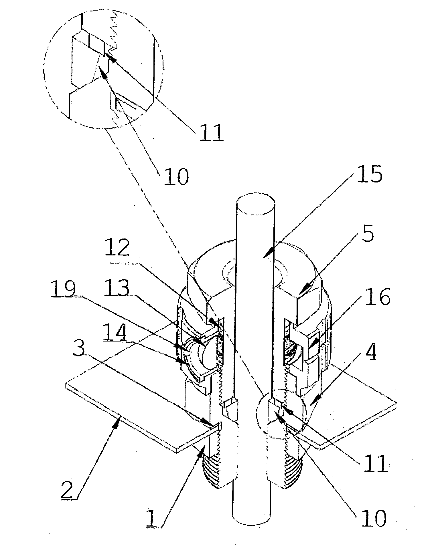
[0024]To solve the problems listed in the previous technique, is included on the cable gland a symbols and / or colors scale, related to the exact pressure to be put on the used cable, within the expected range for each cable gland.

[0025]Said scale can be made with numbers, cable references, letters, etc. The model with colors is the preferred, according to the preferred modality of the present situation, being the alternation of colors on the scale, shown in the marker, compatible with the cable gland (and consequently with the cables) utilized.

[0026]The cable gland can have any size, depending on the cable used. The definition of the scale occurs by testing with the cable gland and its respective cables, in order to determine with precision, the ideal tightening / pressure for each cable, by its corresponding cable gland.

[0027]This way, is possible to obtain a standard sealing procedure for each diameter range of the electric cables. It provides, simultaneously, conditions to the fitt...


PUM

PropertyMeasurementUnit
angleaaaaaaaaaa
PRESSUREaaaaaaaaaa
flexibleaaaaaaaaaa

Abstract

The cable gland with pressure indicator of the present invention comprehends a scale (12) disposed on the sleeve (5) that fits in a body (4), the referred body (4) comprising an optical element box (14) with an optical element (13) inserted in section of its outer surface (16), the positioning of the referred section being determined in a way that the optical element box (14) is positioned above the scale (12) disposed on the sleeve (5), the outer body surface section (4) comprising a reference ring (16).

Description

SUMMARY OF THE INVENTION[0001]The present invention is about a cable gland that indicates to the fitter the exact point of the ideal grip for a proper sealing of the cable used. That way, a standard result for the process is maintained, besides being obtained a record for later inspection.BACKGROUND OF THE INVENTION[0002]The present invention was created after the use, development and testing of equipment for application in hazardous and non-hazardous atmospheres.[0003]Accompanying and observing preliminary tests, it was noted several times that the lack or excess of grip on cable glands was responsible for failure in the equipment tests.[0004]It was noticed then the need of something in the cable gland that could indicate to the fitter the correct grip that must be applied to the cable gland for each cable type utilized.[0005]The cable gland that constitutes the previous technique refers to an accessory for general electric installations, allowing the installation of cables in elec...

Claims


Application Information

Patent Timeline
Patent Type & Authority Applications(United States)
IPC IPC(8): H01B17/58
CPCH01B17/586H02G15/013H02G3/0675F16L5/06H02G3/22
Inventor MARTINS NETO, JOAO
Owner MARTINS NETO JOAO
Why Eureka
Try Eureka