Antennas for small satellites

a technology for satellites and antennas, applied in the field of antennas, can solve the problems of limited power production of satellites with body-mounted solar panels, and achieve the effects of saving transmission power on satellites, high gain, and high gain

Active Publication Date: 2015-06-11
UNIV OF FLORIDA RES FOUNDATION INC
View PDF9 Cites 29 Cited by
  • Summary
  • Abstract
  • Description
  • Claims
  • Application Information

AI Technical Summary

Benefits of technology

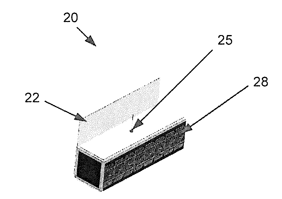
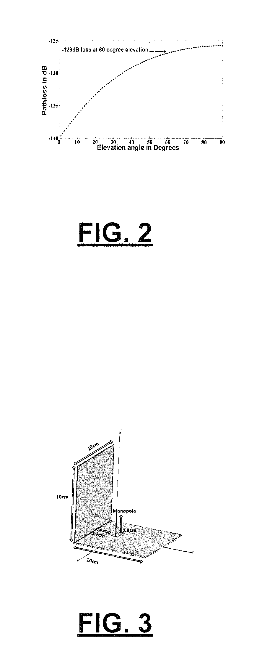
[0005]In comparison to a monopole with a gain of about 1.65 dB used in a conventional Cubesat application at higher frequencies, a monopole packaged according to some embodiments of the present invention provides a gain up to about 10 dB depending on the packaging. Similarly, a patch antenna according to some embodiments of the present invention may provide a gain improvement of a factor of about 2, i.e. about 3 dB, over the gain without packaging considerations. Thus, some embodiments of the present invention are capable of saving transmission power on satellites. Although the discussion herein is directed to antennas for use with satellites, such as a CubeS at, it is understood that the antennas may be used with other non-satellite, high-gain applications (e.g., modems) according to additional embodiments.
[0006]According to one embodiment, an antenna is a high gain S-band reflector antenna explo

Problems solved by technology

A satellite with body-mounted solar panels may be limited in power production

Method used


Image

  • Antennas for small satellites
  • Antennas for small satellites
  • Antennas for small satellites

Examples


Embodiment Construction

[0065]Various embodiments of the present invention will now be described more fully hereinafter with reference to the accompanying figures, in which some, but not all embodiments of the inventions are shown. Indeed, these inventions may be embodied in many different forms and should not be construed as limited to the embodiments set forth herein. Rather, these embodiments are provided so that this disclosure will satisfy applicable legal requirements. Like numbers refer to like elements throughout.

[0066]Details regarding various embodiments of the antennas and methods of assembly within small satellites are described herein. Specifically, some embodiments of the present invention are described with respect to three design reports that are included herein. The first report, entitled “Configuration of 3U CubeSat Structures for Gain Improvement of S-band Antennas,” is a detailed design report of certain embodiments of antennas and setups thereof for use with small satellites. The secon...


PUM


Abstract

Various embodiments of the present invention include assemblies and methods for utilizing antennas with high gain in small satellites. In one embodiment, a satellite comprising a payload configured for transmitting data is provided. The payload may include various components of the satellite, such as the attitude control system, electrical power system, and/or communication system. The satellite may be configured to communicate with one or more ground stations. The satellite includes a support structure comprising at least one deployable panel, wherein the support structure houses the payload. The satellite also includes at least one antenna coupled to the support structure, wherein the deployable panel is configured to cover the antenna in a non-deployed state and to expose the antenna in a deployed state.

Description

CROSS REFERENCE TO RELATED APPLICATIONS[0001]This application is a National Stage application, filed under 35 U.S.C. §371, of International Application PCT / US2013 / 045130 filed Jun. 11, 2013, which claims priority to U.S. Application No. 61 / 658,167 filed Jun. 11, 2012, both of which are hereby incorporated by reference in their entireties.FIELD OF THE INVENTION[0002]Embodiments of the present invention relate to antennas and, more particularly, to antennas for use in small satellites.BACKGROUND[0003]Some satellites, such as nano- and pico-satellites in low earth orbits, unlike their larger counterparts, have more stringent limitations on antenna design due to power constraints that govern the operational frequency and size that defines the space constraints. For high bandwidth applications, higher frequencies with higher transmission power may be used with wide band high gain antenna. Transmission power for a satellite can be reduced by utilizing high gain antennas, but at the cost o...

Claims


Application Information

Patent Timeline
IPC IPC(8): H01Q1/28B64G1/44B64G1/10B64G1/22
CPCH01Q1/288B64G1/105B64G1/443B64G1/222B64G1/66H01Q9/30H01Q19/106
Inventor FITZ-COY, NORMAN G.SHIRVANTE, VIVEKJOHNSON, SHAWNCASON, KATHRYN
Owner UNIV OF FLORIDA RES FOUNDATION INC
Why Eureka
Try Eureka