
Lighting device for obtaining a predetermined light distribution at a target area

Inactive Publication Date: 2015-06-18
KONINKLIJKE PHILIPS ELECTRONICS NV +1
View PDF2 Cites 1 Cited by
  • Summary
  • Abstract
  • Description
  • Claims
  • Application Information

AI Technical Summary

Benefits of technology

The objective of this invention is to create a lighting device that can be placed anywhere while still providing the desired lighting effect. This will be done while keeping energy consumption low.

Problems solved by technology

Thus, the possibility to set the light distribution is limited to choosing the position on a pole before fixing the luminaire in that position.
This in turn results in a clutter of light poles which is not desirable.
More flexibility in placement has already been gained by suspending the luminaires from a wire but this still disturbs the street view with a crisscross of wires.
However, such a lighting device has the drawback of requiring continuous application of a voltage for as long as a desired or required light distribution at a target area needs to be provided.
This in turn results in high energy consumption and a less robust lighting device.

Method used


Image

  • Lighting device for obtaining a predetermined light distribution at a target area
  • Lighting device for obtaining a predetermined light distribution at a target area
  • Lighting device for obtaining a predetermined light distribution at a target area

Examples


Embodiment Construction

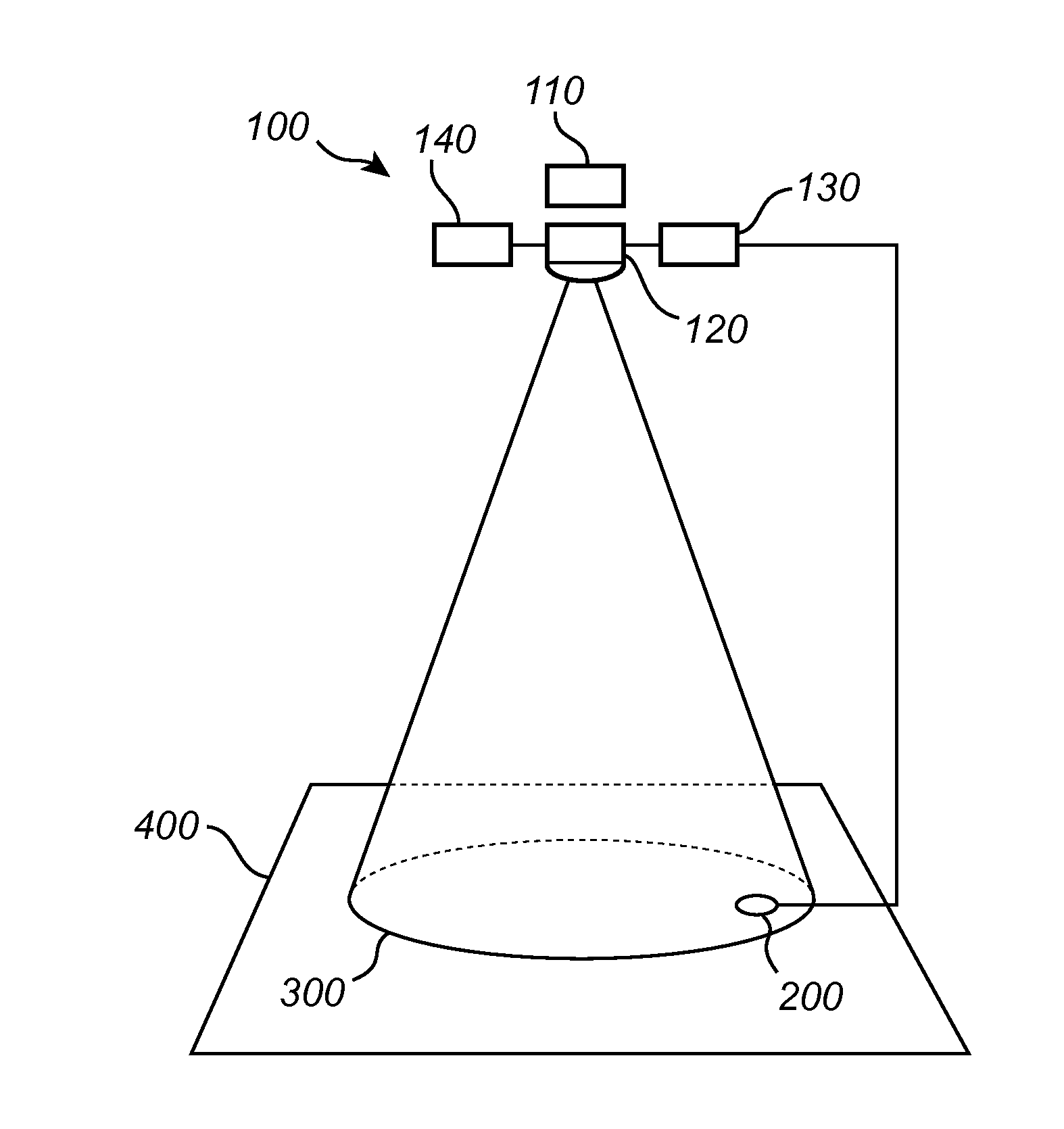
[0039]FIG. 1 shows an embodiment of a lighting device 100 according to the invention.

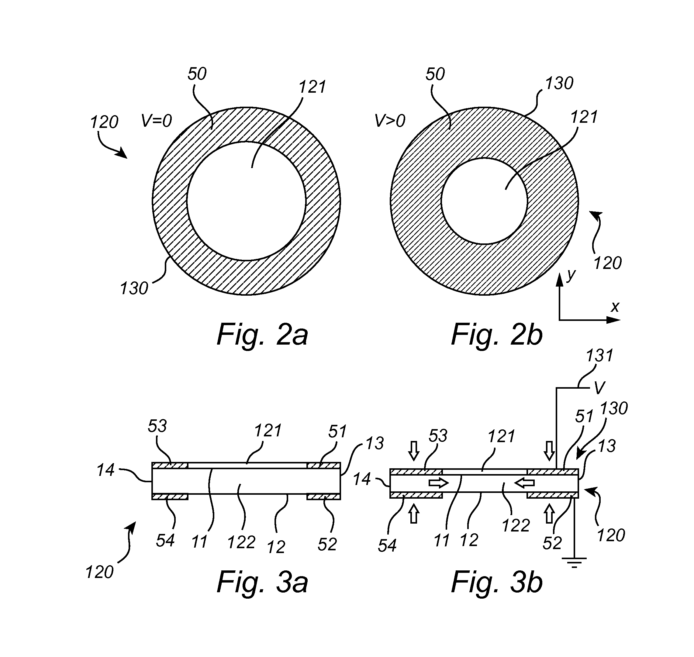
[0040]The lighting device 100 according to the invention generally comprises a light source 110 and an optical component 120. The optical component 120 comprises a substrate 122 and an optical element 121 arranged on a surface of the substrate 122 intended for facing away from the light source 110. The substrate 122 and the optical element 121 may be separate elements, or alternatively the substrate and the optical element may be one and the same element.

[0041]The light source 110 may be any feasible type of light source, for example one or more LEDs or light bulbs, or even an array of light sources. The light source 110 may be arranged on either side of the optical component 120. Preferably, however, the light source 110 is arranged such that light emitted there from first propagates through the substrate 122 of the optical component 120 and then propagates through and / or is reflected by the optica...


PUM


Abstract

The invention relates to a lighting device (100) comprising a light source (110) and an optical component (120) adapted for obtaining a predetermined light distribution (300) at a target area (400). The optical component has a substrate (122) comprising a material that is capable of controllably changing shape when an activating force is applied thereto, and one or more optical elements (121). The substrate further comprises a material capable of being switched from a first state comprising a first static modulus to a second state comprising a second static modulus by means of an external stimulus (140), the first static modulus being smaller than the second static modulus, the static modulus being calculated as the ratio of strain to stress of the substrate under static conditions. This material is capable of controllably changing shape in the first state and being dimensionally stable in the second state, when no activating force is applied thereto.

Description

FIELD OF THE INVENTION [0001]The invention relates to a lighting device comprising a light source and an optical component adapted for obtaining a predetermined light distribution at a target area, the optical component comprising a substrate, the substrate comprising a material being capable of controllably changing shape when an activating force is applied thereto, and one or more optical elements.BACKGROUND OF THE INVENTION[0002]Lighting devices of the above mentioned kind are used in luminaires in principle of any indoors or outdoors type, but particularly luminaires for outdoor lighting applications. Flexibility in placement of luminaires is very much desired. For instance for outdoor lighting, city architects are bound to mount luminaires on a pole at a fixed position relative to the ground in order to obtain a desired or required light distribution at a target area. Thus, the possibility to set the light distribution is limited to choosing the position on a pole before fixing...

Claims


Application Information

Patent Timeline
IPC IPC(8): F21V14/00F21V23/04F21V13/00F21S8/08F21V23/00
CPCF21V14/00F21S8/085F21W2131/103F21V13/00F21V23/0478F21V23/003F21K9/20F21Y2101/00F21V14/003F21V23/045F21V14/06G02B26/0808
Inventor CROMPVOETS, FLORIS MARIA HERMANSZWAGEMANS, WIEBEMATYSEK, MARC
Owner KONINKLIJKE PHILIPS ELECTRONICS NV
Learn More