Thermal Flow Meter

Active Publication Date: 2015-06-18
HITACHI ASTEMO LTD
View PDF8 Cites 3 Cited by
  • Summary
  • Abstract
  • Description
  • Claims
  • Application Information

AI Technical Summary

Benefits of technology

The invention provides a thermal flow meter that can accurately measure the flow of gas in both directions. This makes it easier to provide accurate measurements of gas flow.

Problems solved by technology

However, such case is rare.

Method used


Image

  • Thermal Flow Meter
  • Thermal Flow Meter
  • Thermal Flow Meter

Examples


Embodiment Construction

[0045]A thermal flow meter described in modes for carrying out the invention (hereinafter referred to as embodiments) explained below can maintain a high measurement accuracy in a flow rate measurement of a measurement target gas. This point will be hereinafter explained in details in the embodiments described below, but the overview thereof will be subsequently explained.

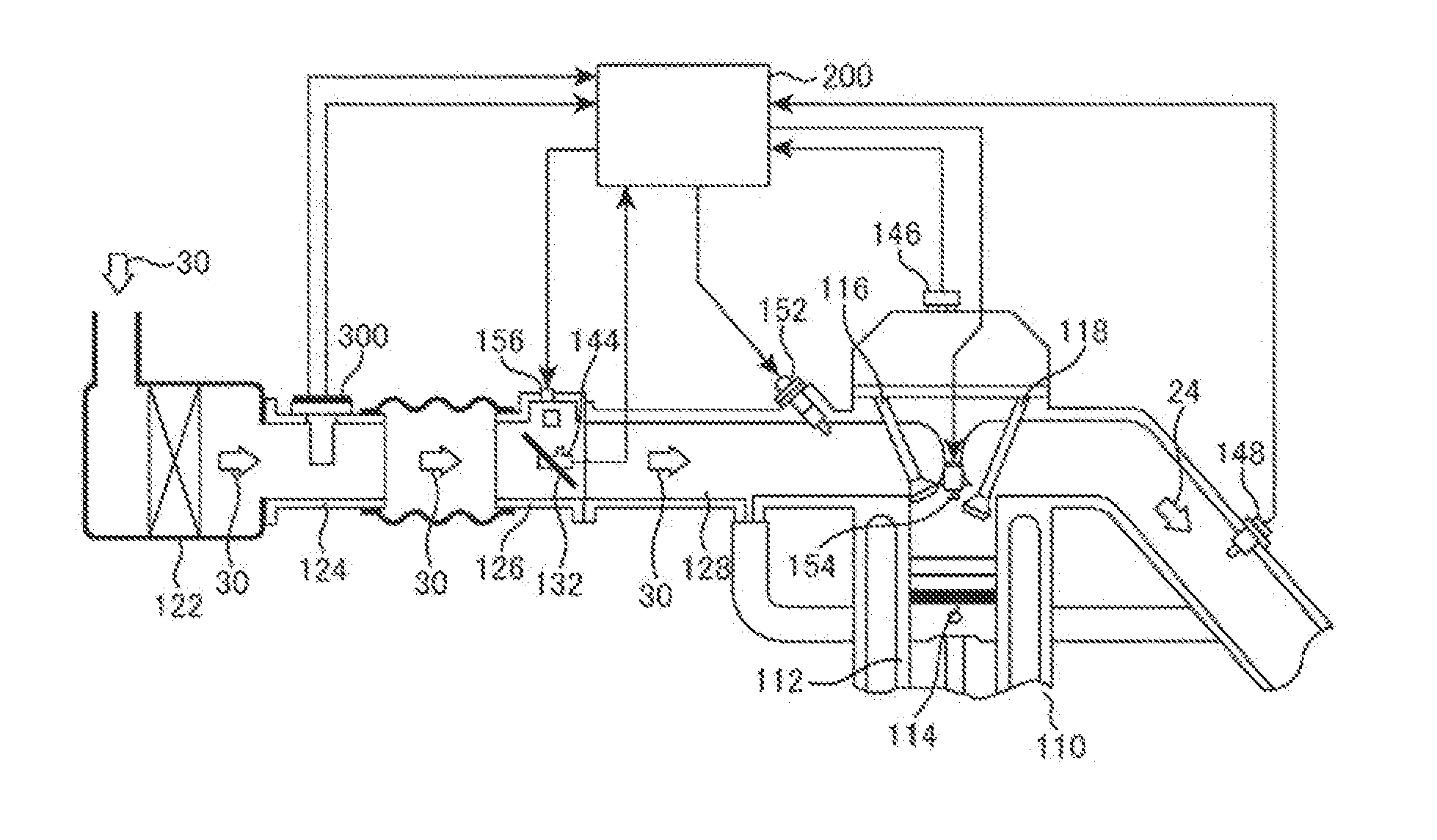
[0046]In the embodiments described below, a thermal flow meter includes a bypass passage receiving a portion of the measurement target gas flowing in the main passage and passing the measurement target gas. The bypass passage has an inlet port and an exit, and a flow rate measurement passage unit for measuring the flow rate of the measurement target gas is provided in the bypass passage between the inlet port and the exit. In the flow rate measurement passage unit, heat transfer is performed between the flow rate measurement circuit and the measurement target gas in the bypass passage, so that the flow rates of the...


PUM


Abstract

A thermal flow meter capable of measuring flow rates of a gas flowing in a forward direction and a backward direction with a high degree of accuracy is provided. A thermal flow meter 300 according to the present invention includes a bypass passage configured to retrieve and flow a measurement target gas 30 received from a main passage 124 and a flow rate measurement circuit 601 configured to measure a flow rate by performing heat transfer with the measurement target gas flowing in the bypass passage. In an outlet port side chamber 4216 provided at an upstream with respect to an outlet port 352 of the bypass passage which is formed to be open in a downstream direction in a flow direction of the measurement target gas, a guide 4217 is provided to oppose the outlet port to change a direction of a flow of the measurement target gas flowing in from the opposite side, and the outlet port and an inflow unit of the outlet port side chamber are arranged to be eccentric when they are seen in a direction along the flow direction of the measurement target gas flowing in the main passage.

Description

TECHNICAL FIELD[0001]The present invention relates to a thermal flow meter for measuring a flow rate of a gas.BACKGROUND ART[0002]When a measurement target gas which is to be measured by a thermal flow meter flows in a state of a laminar flow only in a forward direction, it is easy to measure the flow rate of the measurement target gas. However, such case is rare. In many cases, not only a flow in the forward direction but also a flow in the backward direction may occur in the measurement target gas, and in addition, a vortex may be generated.[0003]For example, when a thermal flow meter is provided in a vehicle to be used to measure the flow rate of intake air guided into an internal combustion engine, the intake air which is the measurement target gas flows in a state of pulsing motion based on the operation of the internal combustion engine, and further, in a particular operation range of the internal combustion engine, a backward flow phenomenon occurs in a mixed manner, in which...

Claims


Application Information

Patent Timeline
IPC IPC(8): G01F1/684G01F1/696G01F5/00
CPCG01F1/684G01F1/696G01F5/00G01F1/6842G01F1/6845G01F1/6965G01F15/14
Inventor MORINO, TAKESHITASHIRO, SHINOBUTOKUYASU, NOBORUHANZAWA, KEIJIINOUE, ATSUSHI
Owner HITACHI ASTEMO LTD
Why Eureka
Try Eureka