
Image forming apparatus, image forming method, and non-transitory computer readable medium storing control program

Active Publication Date: 2015-06-18
KONICA MINOLTA INC
View PDF1 Cites 9 Cited by
  • Summary
  • Abstract
  • Description
  • Claims
  • Application Information

AI Technical Summary

Benefits of technology

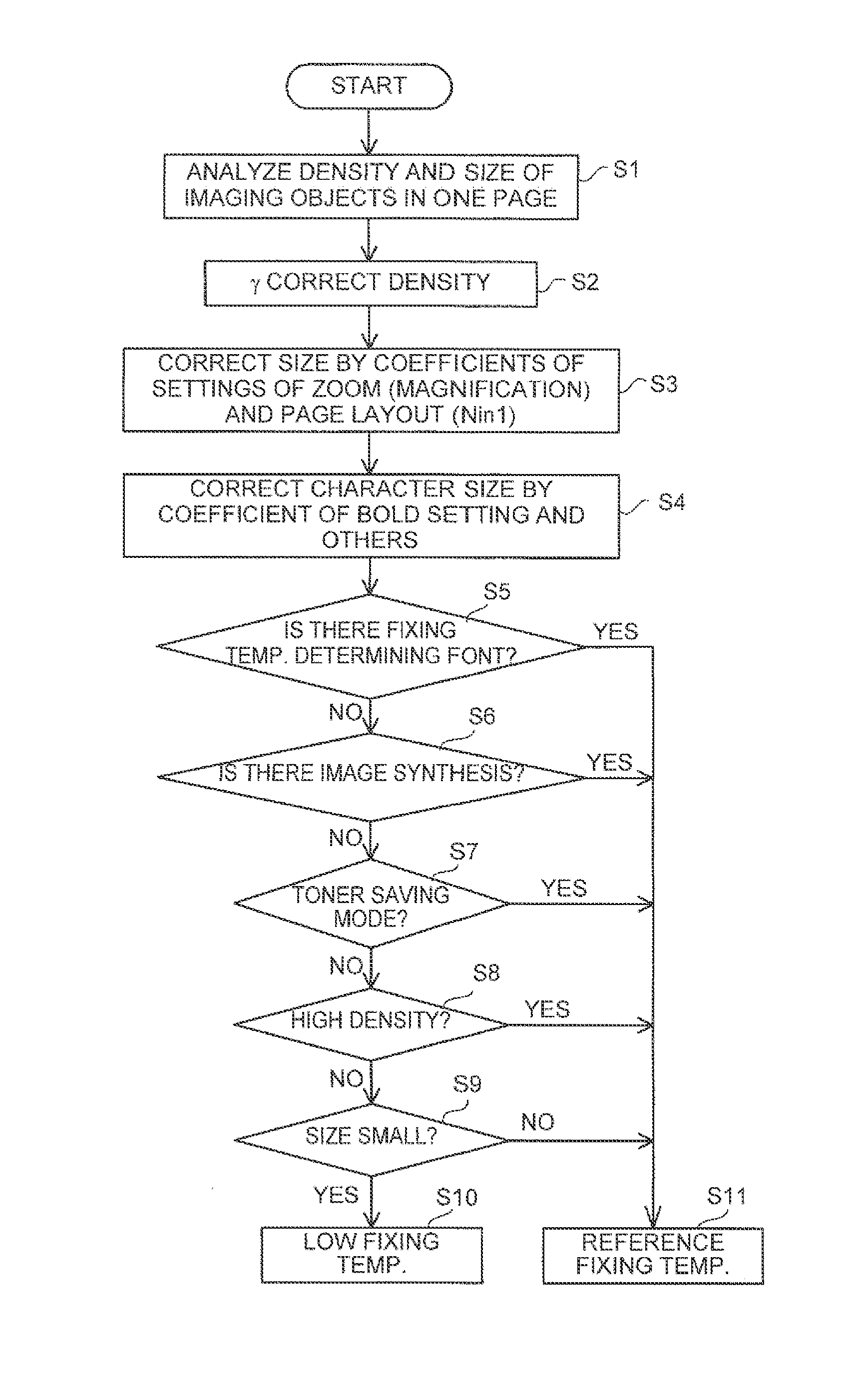
This patent is about an image forming apparatus that uses a minimum fixing temperature to save energy and prevent fixing failures. It adjusts the temperature of the fixing section based on the size and density of the image being formed. By doing so, it reduces energy consumption and prevents image quality issues.

Problems solved by technology

This is because those drawing objects are likely to cause fixing failures at a low fixing temperature.

Method used


Image

  • Image forming apparatus, image forming method, and non-transitory computer readable medium storing control program
  • Image forming apparatus, image forming method, and non-transitory computer readable medium storing control program
  • Image forming apparatus, image forming method, and non-transitory computer readable medium storing control program

Examples


Embodiment Construction

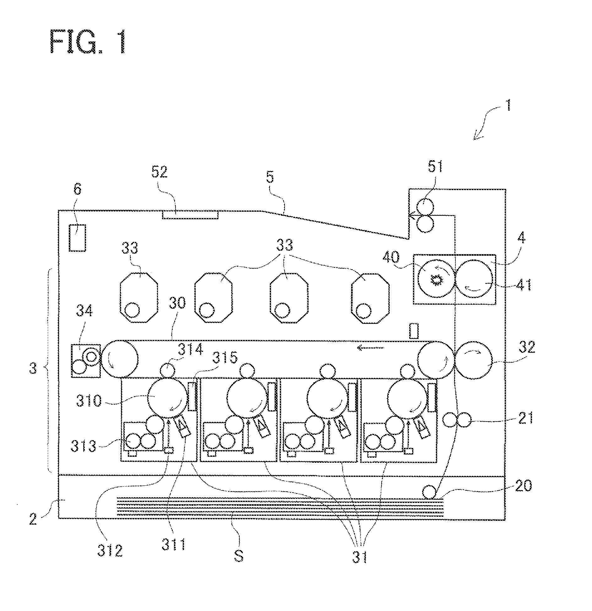
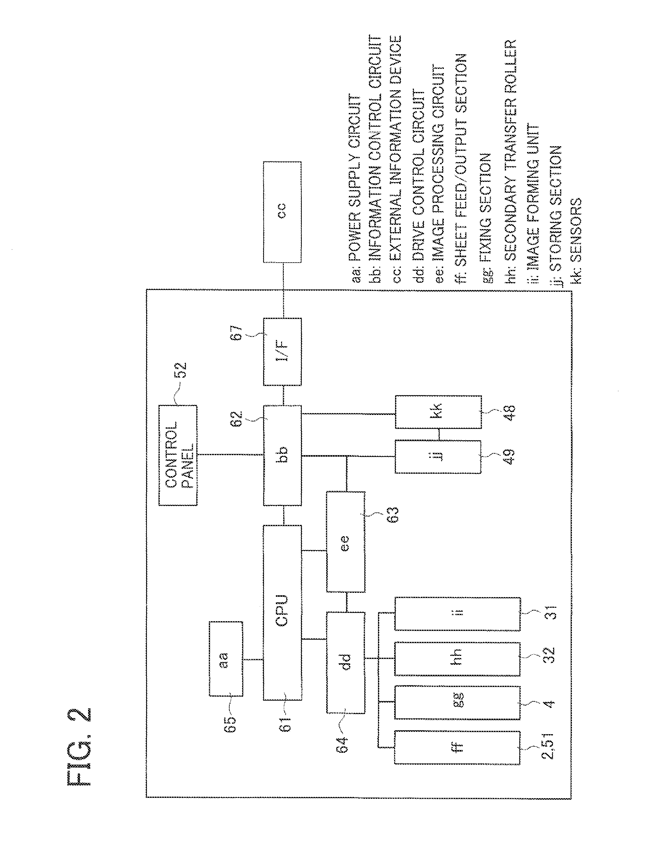
[0023]A detailed description of a preferred embodiment of the present invention will now be given referring to the accompanying drawings. In the present embodiment, the invention is applied to an image forming apparatus 1 shown in FIG. 1. The image forming apparatus 1 in FIG. 1 includes a sheet feeding section 2, an image forming section 3, and a fixing section 4. The sheet feeding section 2 is configured to store recording mediums S such as printing sheets to be subjected to image formation in the image forming section 3 and feed the recording mediums S one by one. The image forming section 3 is configured to form a toner image and transfer this toner image to a recording medium S fed from the sheet feeding section 2. The fixing section 4 is configured to heat the recording medium S to which the toner image has been transferred, thereby fixing the toner image to the recording medium S. The image forming apparatus 1 is further provided with a sheet output tray 5 on which the recordi...


PUM


Abstract

An image forming apparatus includes an image forming section to form a toner image and transfer the toner image to a recording medium and a fixing section to heat the recording medium transferred with the toner image and further an image analyzing section to extract a density value or a size value of an imaging object included in an image, and a temperature determining section to determine a minimum fixing temperature based on the density value or size value of the imaging object included in a page image. The temperature determining section determines the minimum fixing temperature to be lower when a highest one of the density values is lower than when the highest value is higher or determines the minimum fixing temperature to be lower when a largest one of the size values is smaller than when the largest size value is larger.

Description

CROSS-REFERENCE TO RELATED APPLICATIONS[0001]This application is based upon and claims the benefit of priority from the prior Japanese Patent Application No. 2013-260789 filed on Dec. 18, 2013, the entire contents of which are incorporated herein by reference.BACKGROUND OF THE INVENTION[0002]1. Field of the Invention[0003]The present invention relates to an image forming apparatus configured to carry a toner image on a recording medium and then fix the toner image to the recording medium by heat to form an image and, more particularly, to an image forming apparatus arranged to optimize input energy to a fixing section according to conditions of output images.[0004]2. Description of Related Art[0005]An image forming apparatus using toner is conventionally configured to form a toner image and then transfer the toner image to a recording medium such as a printing sheet. The toner image transferred to the recording medium is thereafter fixed to the recording medium by heating. Meanwhile...

Claims


Application Information

Patent Timeline
IPC IPC(8): G03G15/20
CPCG03G15/2039G03G15/5025
Inventor TANAKA, TOSHIAKIISHIHARA, YASUHIROMASUMOTO, KOSUKECHIKAZAWA, SATOSHI
Owner KONICA MINOLTA INC
Learn More