Method and related apparatus for establishing link-diverse traffic paths in a telecommunications network

a technology of link-diverse traffic and telecommunications network, applied in the field of telecommunications, can solve the problems of increasing network resources, adding additional penalties to the network planning process and the network operation, and somehow restricting the solution

Active Publication Date: 2015-06-18
RPX CORP
View PDF10 Cites 11 Cited by
  • Summary
  • Abstract
  • Description
  • Claims
  • Application Information

AI Technical Summary

Benefits of technology

[0011]A problem of the present invention is to achieve path diversity for dual-homed UNI-clien...

Problems solved by technology

This solution is somehow restrictive.
Moreover, it requires more network resources and a...

Method used


Image

  • Method and related apparatus for establishing link-diverse traffic paths in a telecommunications network
  • Method and related apparatus for establishing link-diverse traffic paths in a telecommunications network
  • Method and related apparatus for establishing link-diverse traffic paths in a telecommunications network

Examples


second embodiment

[0040]The a second embodiment, it is assumed that provider SRLG IDs are either not available or not shareable (based on provider network operator policy) with the CE. For this case, a mechanism is described where information signalled to the PE on UNI messages does not require shared knowledge of provider SRLG IDs to support LSP diversity for the overlay extension model. Both approaches follow the L1VPN framework defined in RFC4847, which is incorporated by reference herein. While both methods could be implemented in the same PE network, it is likely that an L1VPN CE network would use only one mechanism at a time.

[0041]PE SRLG information can be used directly by a CE if the CE understands the context, and the CE view is limited to its L1VPN context. In this case, there is a dependency on the provider information and it is thus preferable to be able to query the SRLG in the provider network.

[0042]It may, on the other hand, be preferable to avoid this dependency and to decouple the SR...

first embodiment

[0045]The first embodiment employing an exchange of SRLG information between the PEs via the CE device will now be described in more detail.

[0046]SRLG information is defined in RFC4202 and if the SRLG information of an LSP is known, it can be used to calculate a path for another LSP that is SRLG diverse with respect to an existing LSP.

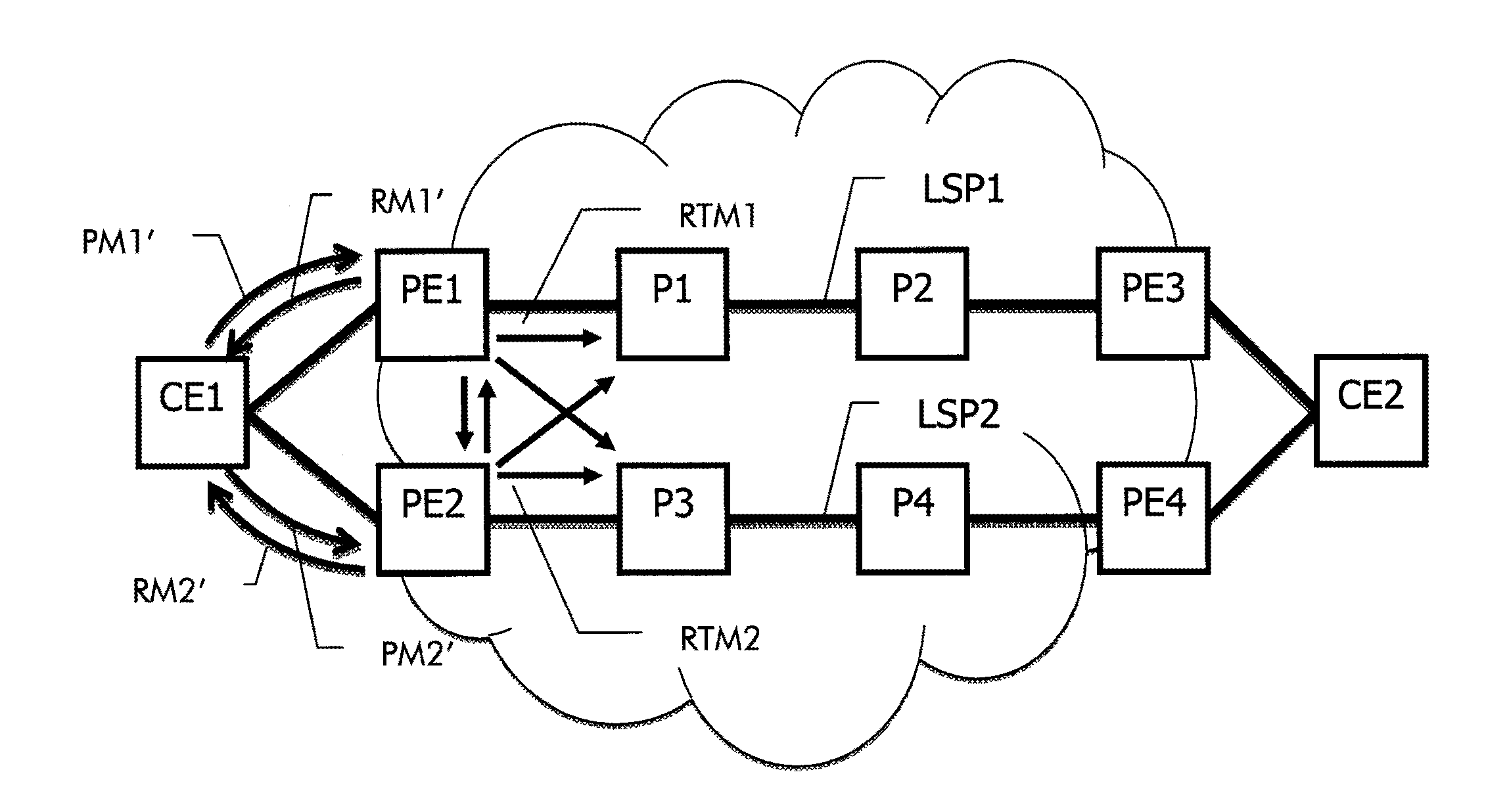
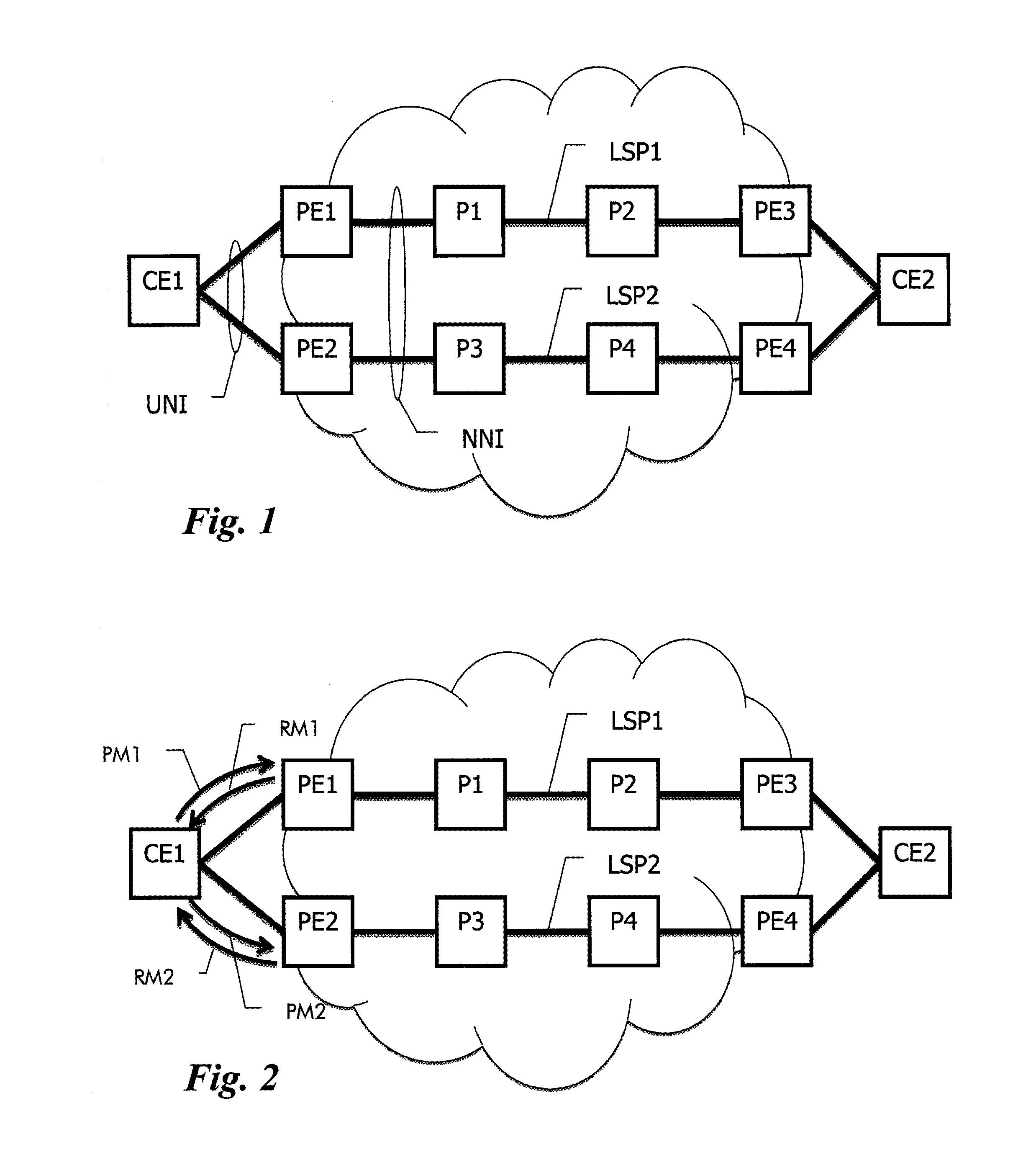
[0047]For example, CE1 in FIG. 1 may have requested an LSP1 from CE1 to CE2 via PE1 and PE3. CE1 could subsequently request an LSP2 to CE2 via PE2 and PE3 with the requirement that it should be maximally SRLG disjoint with respect to LSP1. Since PE2 does not have any information about LSP1, PE2 would need to know the SRLG information associated with LSP1. According to the embodiment, CE1 would request the SRLG information of LSP1 from PE1, and then transparently pass this information to PE2 as part of the LSP2 setup request. PE2 is therefore capable of calculating a path for LSP2 that is SRLG disjoint with respect to LSP1.

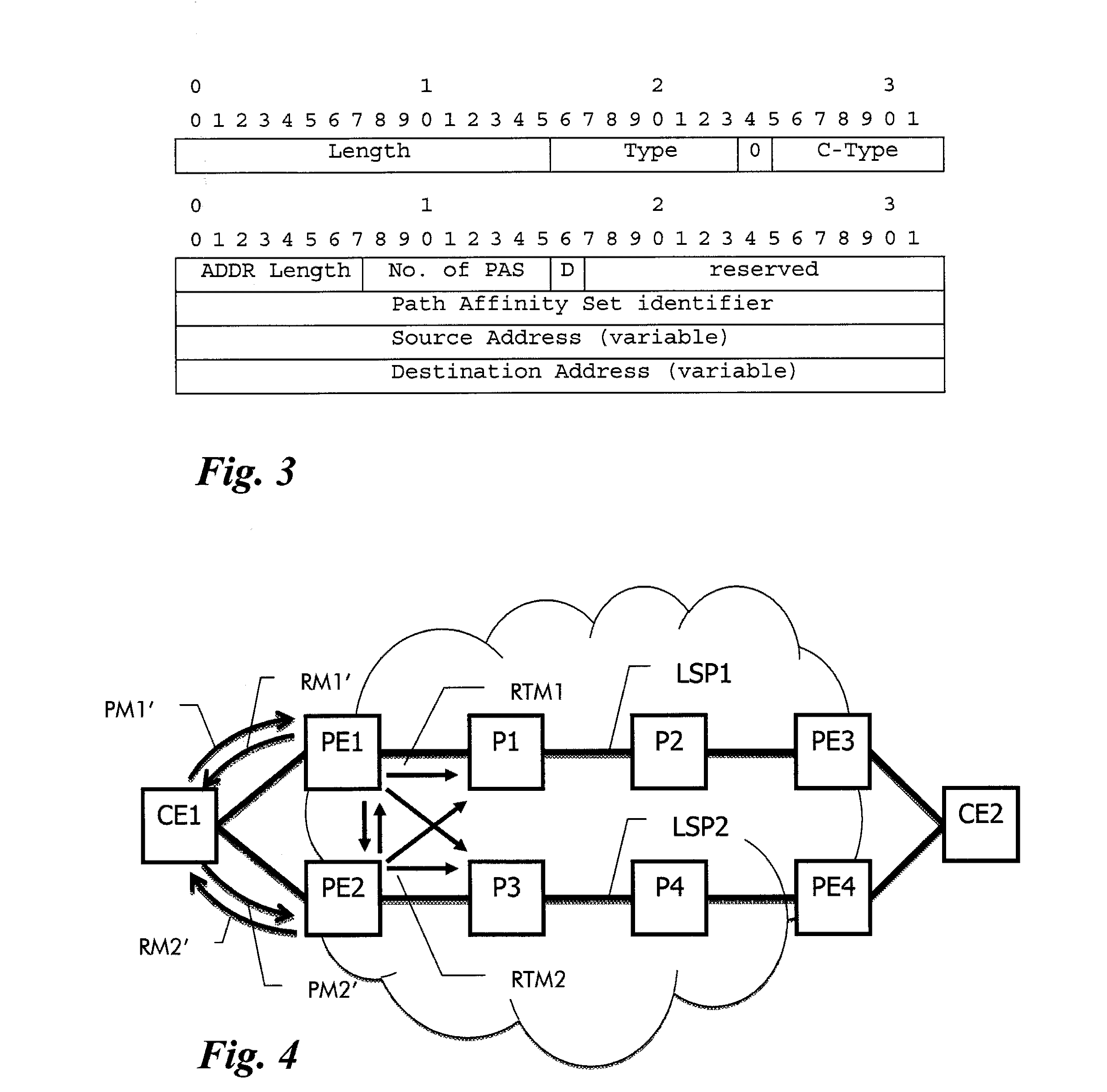
[0048]The exchange of SRLG inf...


PUM


Abstract

In order to achieve path diversity for dual-homed User-Network Interface clients connected to a Generalized Multiprotocol Label Switching control plane enabled transport network that is operated in an overlay mode, the overlay extension service model is enhanced by adding shared constraint information for path diversity in the optical transport network. In particular, within the provider network, shared constraint information of a first traffic path is determined and a data element indicative of the shared constraint information is returned by a first provider edge node to a customer edge device via a User-Network Interface. When the customer edge device requests a second traffic path through the provider network to be established from a second provider edge node and to be disjoint from said first traffic path, the customer edge device forwards the data element to the second provider edge node to enable path calculation of the second traffic path using the shared constraint information as exclusion list.

Description

FIELD OF THE INVENTION [0001]The present invention relates to the field of telecommunications and more particularly to a method and related apparatus for establishing link-diverse traffic paths in a telecommunications network.BACKGROUND OF THE INVENTION[0002]In classical layer 1 transport networks employing time-division multiplexing (TDM) and / or wavelength division multiplexing (WDM), such as the Optical Transport Network (OTN) or the Synchronous Digital Hierarchy (SDH), techniques have been established to support dynamic resource allocation and setup of traffic paths. A transport network, which allows traffic paths to be set up through a switched network automatically is termed Automatically Switched Transport Network (ASTN) or Automatically Switched Optical Network (ASON). The WDM layer is often also called layer 0.[0003]Traditionally, creating traffic paths through a series of Network Elements has involved configuration of individual cross-connections on each network element. AS...

Claims


Application Information

Patent Timeline
IPC IPC(8): H04L12/707H04L12/803H04Q11/00H04L45/128H04L45/24H04L45/243H04L45/50H04L47/724
CPCH04L45/24H04Q11/0066H04L47/125H04Q2011/0081H04Q2011/0073H04Q2011/0086H04Q2011/0077H04L45/128H04L45/50
Inventor BELLER, DIETERFEDYK, DONALD
Owner RPX CORP
Why Eureka
Try Eureka