Zoom lens, and imaging apparatus equipped with same

a technology of zoom lens and imaging apparatus, which is applied in the field of zoom lens and camera device, can solve the problems of deteriorating image quality and making a photographer feel unpleasant, and achieve the effect of reducing the whole longitudinal dimension and reducing the telephoto ratio

Active Publication Date: 2015-06-25
TAMRON
View PDF1 Cites 10 Cited by
  • Summary
  • Abstract
  • Description
  • Claims
  • Application Information

AI Technical Summary

Benefits of technology

[0042]Appropriately prescribing a composite focal length of the lens groups behind the second negative lens group and closer to the image plane during f

Problems solved by technology

Meanwhile, when the displacement along the optical axis of the focusing lens groups causes a field angle to vary, and then an imaging magnification to vary, beams in

Method used


Image

  • Zoom lens, and imaging apparatus equipped with same
  • Zoom lens, and imaging apparatus equipped with same
  • Zoom lens, and imaging apparatus equipped with same

Examples


embodiment 1

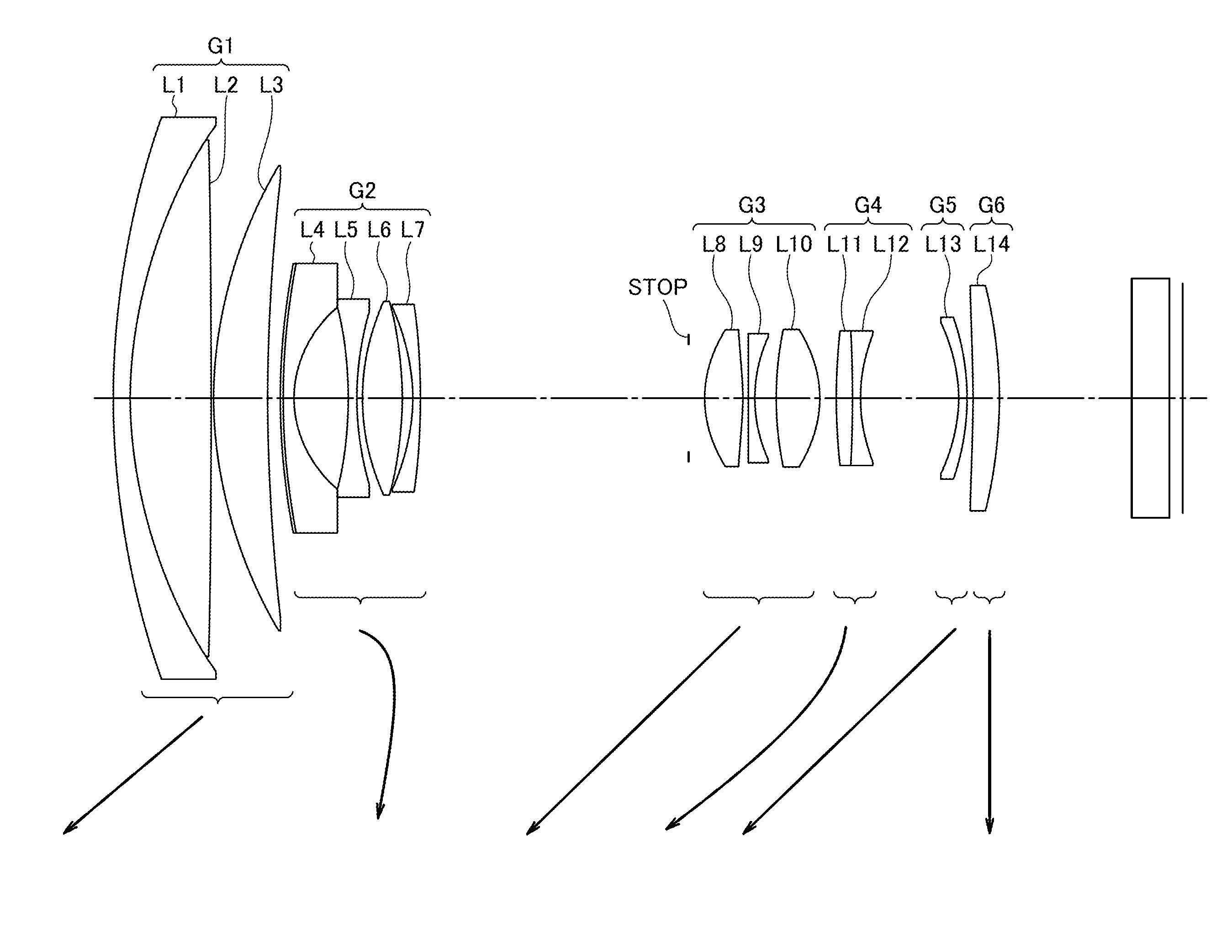
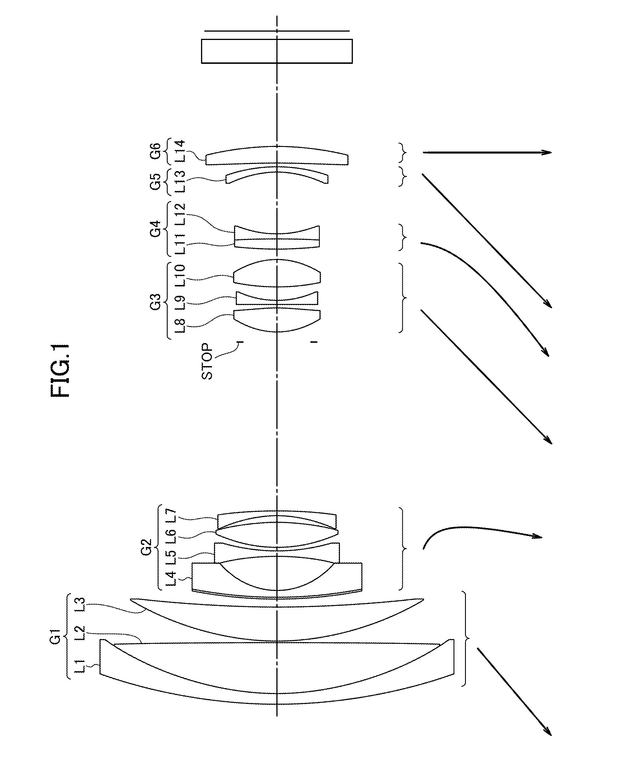
[0061]A first embodiment of the zoom lens comprises a first positive lens group G1 of plus refractive power, a first negative lens group G2 of minus refractive power, another or second positive lens group G3 of plus refractive power, another or second negative lens group G4 of minus refractive power, and additional lens group A G5 of minus refractive power and lens group B G6 of plus refractive power arranged serially in order on the closest to an object first basis.

[0062]The first positive lens group G1 is comprised of a cemented lens of two lens pieces, namely, a negative power meniscus lens piece L1 positioned the closest to the object and having its convex surface faced toward the object and a positive power lens piece L2, and a positive power meniscus lens piece L3 positioned the farthest from the object and having its convex surface faced toward the object.

[0063]The second negative lens group G2 is comprised of a negative power meniscus lens piece L4 having its front side shap...

embodiment 2

[0075]A second embodiment of the zoom lens comprises a first positive lens group G1 of plus refractive power, a first negative lens group G2 of minus refractive power, another or second positive lens group G3 of plus refractive power, another or second negative lens group G4 of minus refractive power, and additional lens group A G5 of minus refractive power and lens group B G6 of plus refractive power serially arranged in order on the closest to an object first basis.

[0076]The first positive lens group G1 is comprised of a cemented lens of two lens pieces, namely, a negative power meniscus lens piece L1 the closest to the object and having its convex surface faced toward the object and a positive power lens piece L2, and a positive power meniscus lens piece L3 having its convex surface faced toward the object.

[0077]The first negative lens group G2 is comprised of a negative power meniscus lens piece L4 the closest to the object and having its aspherical surface faced toward the obje...

embodiment 3

[0088]A third embodiment of the zoom lens comprises a first positive lens group G1 of plus refractive power, a first negative lens group G2 of minus refractive power, another or second positive lens group G3 of plus refractive power, another or second negative lens group G4 of minus refractive power, additional lens group A G5 of minus refractive power and lens group B G6 of plus refractive power serially arranged in order on the closest to an object first basis.

[0089]The first positive lens group G1 is comprised of a cemented lens of two lens pieces, namely, a negative power meniscus lens piece L1 the closest to the object and having its convex surface faced toward the object and a positive power lens piece L2, and a positive power meniscus lens piece L3 having its convex surface faced toward the object.

[0090]The first negative lens group G2 is comprised of a negative power meniscus lens piece L4 the closest to the object and having its front side shaped in aspherical surface and i...


PUM


Abstract

A zoom lens exhibits a reduction in size, increased magnification, a reduction in variation of angle of view during zooming, and an increased focusing speed, said zoom lens being suitable for an imaging apparatus using a solid-state imaging device such as an interchangeable lens, a digital still camera, a digital video camera, or the like. The zoom lens has, in the lens system, at least: a first negative lens group having negative refractive power; a second negative lens group disposed further towards the image side than the first negative lens group, and which has negative refractive power; and a lens group (A) disposed so as to be adjacent to the image side of the second negative lens group. In the zoom lens, focusing from an infinite distance to a near object is performed by moving only the second negative lens group towards the image side, and prescribed conditions are satisfied.

Description

FIELD OF THE INVENTION[0001]The present invention relates to zoom lenses and camera devices incorporating the same, and more particularly, compact, light-weight, and high-speed focusing zoom lenses and camera devices incorporating the same.BACKGROUND ART[0002]As imaging optical systems dedicated to digital input / output apparatuses such as digital still cameras, digital video cameras, and the like, compact and light-weight zoom lenses capable of focusing on an object within close-up photographing range have been desired, and moreover, also desired have been camera devices incorporating zoom lenses capable of high-speed focusing on an object within close-up photographing range.[0003]For the recent years, camera devices, such as digital still cameras, employing solid state image sensors have become increasingly popular. Especially, exchangeable lens systems in single-lens reflex style have been popular so far, which exploit phase difference sensors and distance data output therefrom, f...

Claims


Application Information

Patent Timeline
IPC IPC(8): G02B15/16H04N5/232G02B13/00
CPCG02B15/16H04N5/23296G02B13/0015G02B13/009G02B13/18G02B15/20G02B15/145105G02B15/1461H04N23/69
Inventor IWASAWA, YOSHITO
Owner TAMRON
Why Eureka
Try Eureka