
Dental prosthesis and its manufacturing method

a technology for dental prostheses and manufacturing methods, applied in dental prostheses, fastening prostheses, medical science, etc., can solve the problems of degeneration or exposure of dental pulp, inability to restore the original occlusal form, and long time and money to fix artificial teeth, etc., to achieve no time of restoration, promote dental health, and restore teeth

Inactive Publication Date: 2015-07-02
PHOTONIC SYST INTEGRATION LLC
View PDF21 Cites 0 Cited by
  • Summary
  • Abstract
  • Description
  • Claims
  • Application Information

AI Technical Summary

Benefits of technology

This patent is about a dental prosthesis and its manufacturing method. The invention aims to fix an artificial tooth to an adjacent tooth without the need for grinding the adjacent tooth, which can promote dental health and restore teeth even in patients who have hypertension or angina pectoris. The dental prosthesis restores the tooth with no grinding or influence on the dental pulp, conserves enamel, which is the hardest in the human body, keeps the present occlusion state, prevents decay of teeth, does not cause a foreign substance, reducing medical accidents, reduces medical consultation hours, and can be easily removed when necessary. Therefore, the dental prosthesis is the most human-friendly.

Problems solved by technology

However, the conventional crown bridge has several disadvantages in that it causes degeneration or exposure of dental pulp, or hypersensitivity since a loss of tooth substance is increased, and in that it is impossible to restore the original occlusal form due to the grinding of the occlusal surface of the adjacent teeth.
However, the implant has several disadvantages in that it takes much time and money to fix the artificial tooth, has limitations in restoration in the case of patients of severe periodontal disease, wasting diseases, diabetes and hematologic diseases, and is relatively weak to lateral pressure.
In the prior art prostheses, it is difficult to apply various prostheses according to conditions of adjacent teeth, since it is unavoidable to form holes in the adjacent teeth or grind the adjacent teeth to hold the fixed state of the prostheses.
However, such conventional method has a disadvantage in that it is difficult to obtain holding force to the maximum.

Method used


Image

  • Dental prosthesis and its manufacturing method
  • Dental prosthesis and its manufacturing method
  • Dental prosthesis and its manufacturing method

Examples


Embodiment Construction

[0050]Reference will now be made in detail to embodiments of the present invention, examples of which are illustrated in the accompanying drawings.

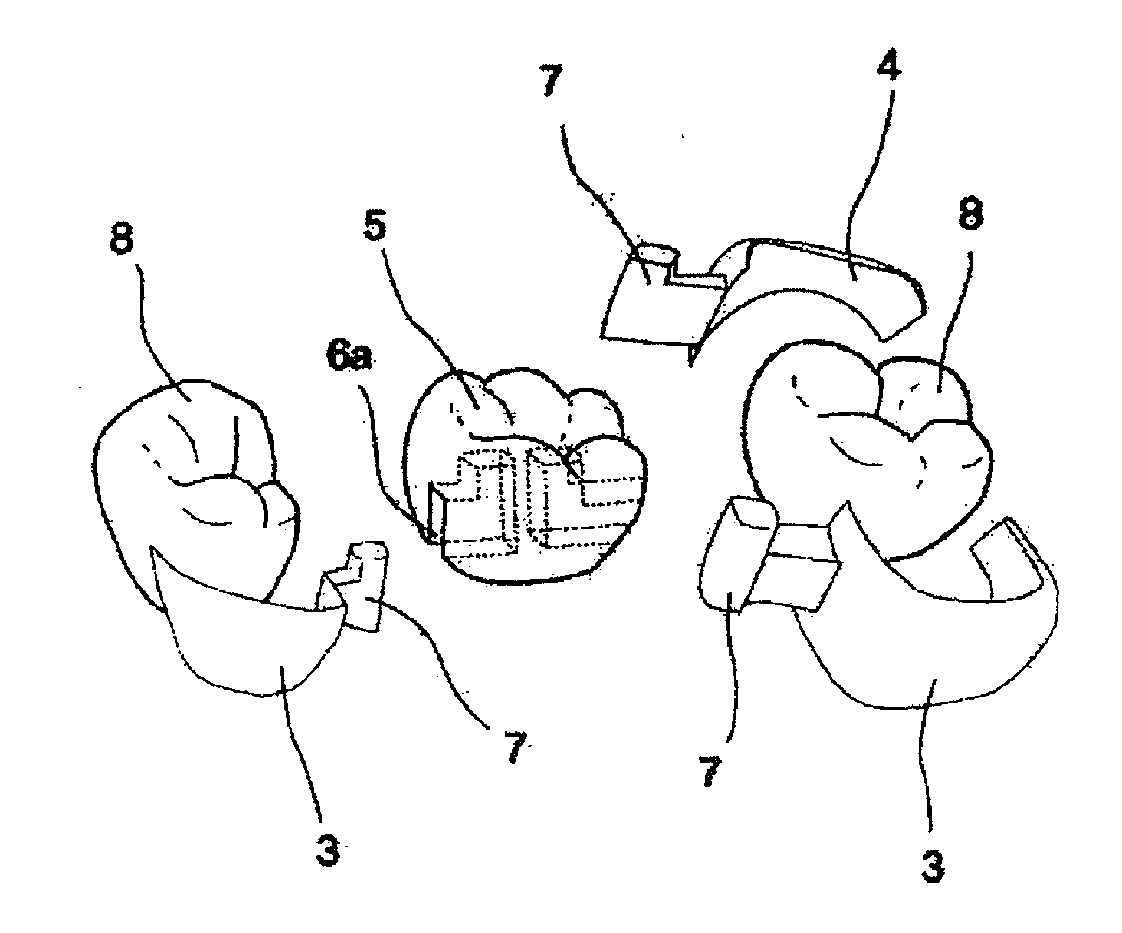
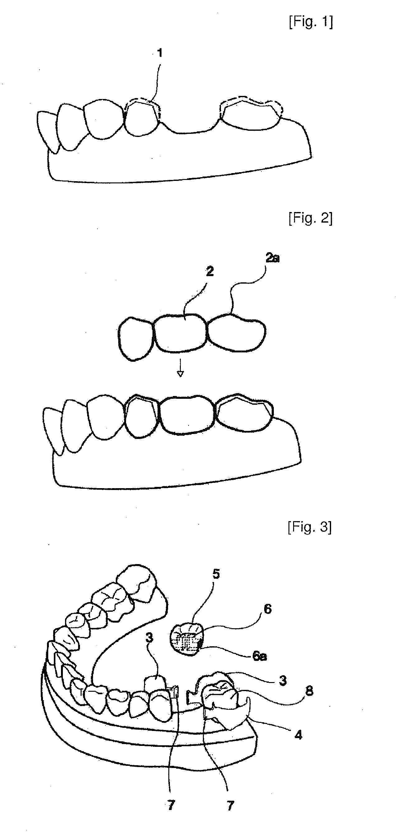
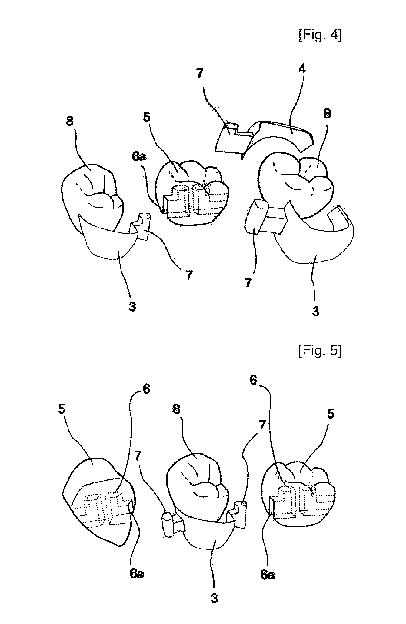
[0051]FIGS. 3 to 17 are views showing a dental prosthesis according to a embodiment of the present invention.

[0052]As shown in FIGS. 3 and 4, the dental prosthesis according to the present invention includes: an artificial tooth 5 having female members 6 and slots 6a; and holding parts 3 and 4 respectively having male members 7 formed integrally with the holding parts 3 and 4 and inserted into the female members 6 and the slots 6a of the artificial tooth 5, and fixed to an adjacent tooth 8.

[0053]Combining force between the holding parts 3 and 4 and the adjacent tooth 8 is increased by maximizing an area of the holding parts 3 and 4, and combining force between the holding parts 3 and 4 and the artificial tooth 5 is increased by maximizing an area of the female member 6 and the male member 7. At this time, sizes of the female member 6 and ...


PUM


Abstract

Disclosed herein are a dental prosthesis and its manufacturing method for restoring a lost tooth. The dental prosthesis has a male member formed on a holding part attached on an adjacent tooth for attaching an artificial tooth on the adjacent tooth and a female member formed in the artificial tooth so that the artificial tooth and the adjacent tooth can be connected with each other without grinding the adjacent tooth. The method for manufacturing the dental prosthesis includes the steps of duplicating an original model, waxing up the duplicated model, holding a sprue on the duplicated model in a state where the duplicated model is waxed up, and investing, burning out and casting the duplicating model.

Description

TECHNICAL FIELD[0001]The present invention relates to a dental prosthesis and its manufacturing method for restoring lost tooth, and more particularly, to a dental prosthesis which has a male member formed on a holding part attached on an adjacent tooth for attaching an artificial tooth on the adjacent tooth and a female member formed in the artificial tooth so that the artificial tooth and the adjacent tooth can be connected with each other without grinding of the adjacent tooth, and a method for manufacturing the dental prosthesis which includes the steps of duplicating an original model, waxing up the duplicated model, holding a sprue on the duplicated model in a state where the duplicated model is waxed up, and investing, burning out and casting the duplicated model.BACKGROUND ART[0002]In general, to restore a lost tooth, an adjacent tooth located by the side of an artificial tooth to be restored is ground, and a crown made of metal or ceramic material is covered on the ground a...

Claims


Application Information

Patent Timeline
Patent Type & Authority Applications(United States)
IPC IPC(8): A61C13/225
CPCA61C13/225A61C13/26A61C13/265A61C13/0003
Inventor KWON, OH-DAL
Owner PHOTONIC SYST INTEGRATION LLC
Learn More