Motion control device based on winding string
a technology of motion control and winding string, which is applied in the direction of manufacturing tools, instruments, and ringing, etc., can solve the problems of increasing the volume of the globe type wearing robot, increasing the cost of manufacturing, and increasing the complexity of the method of wearing and removing the glove, so as to achieve efficient adjustment of the length of the string and large force
- Summary
- Abstract
- Description
- Claims
- Application Information
AI Technical Summary
Benefits of technology
Problems solved by technology
Method used
Image

Examples
first embodiment
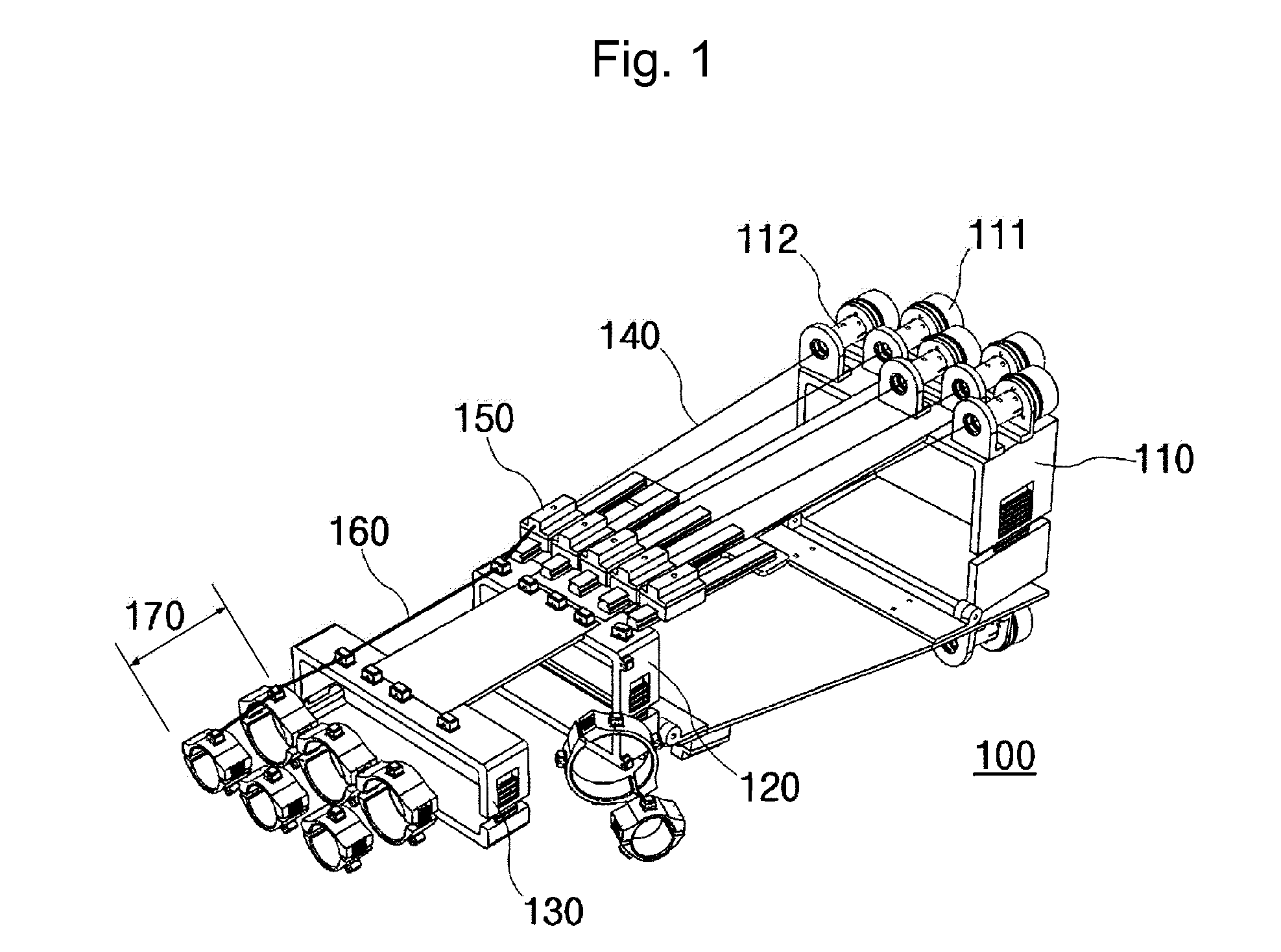
[0044]Referring to FIG. 1, the motion control device 100 includes one or more frames 110 to 130 that support an exoskeleton of a body, strings 140, 160 that connect between the frames 110 to 130, and a motor 111 that is connected to the strings 140, 160 to control the strings 140, 160.
[0045]The body is a concept that includes person, animal and robot having movable parts. In general, in order to move the body, it is necessary to have the exoskeleton around the joint. In FIG. 1, the body is defined as “person”, and the frames are described as being formed in the person exoskeleton.
[0046]For example, the frames 110 to 130 can be configured to include a forearm frame 110 for supporting an exoskeleton of a mid forearm, a wrist frame 120 for supporting an exoskeleton of a wrist, and a palm frame 130 for supporting an exoskeleton of a palm.
[0047]The person's finger can be formed with a joint 170 which is formed of an elastic material to match the joints of the finger. Such a joint 170 is...
second embodiment
[0077]Referring to FIG. 7, a motion control device 200 of a second embodiment can include a first frame 210, a second frame portion 220, a motor 230, a string 240, a pulley 250, a coupling 260 and a separator 270.
[0078]The first frame 210 supports the upper exoskeleton of the body. For example, the first frame 210 is disposed on the exoskeleton located in an upper direction (sky direction) around the joint site of the body to be able to support the upper exoskeleton.
[0079]The second frame 220 supports the lower exoskeleton connected to the upper exoskeleton. For example, the second frame 220 is disposed in the exoskeleton positioned in a lower direction (ground surface direction) around the joint site of the body to be able to support the lower exoskeleton.
[0080]That is, the first frame 210 and the second frame 220 can be disposed at a site that moves in a predetermined direction based on the joint site of the body, respectively.
[0081]The string 240 connects the first frame 210 and ...
third embodiment
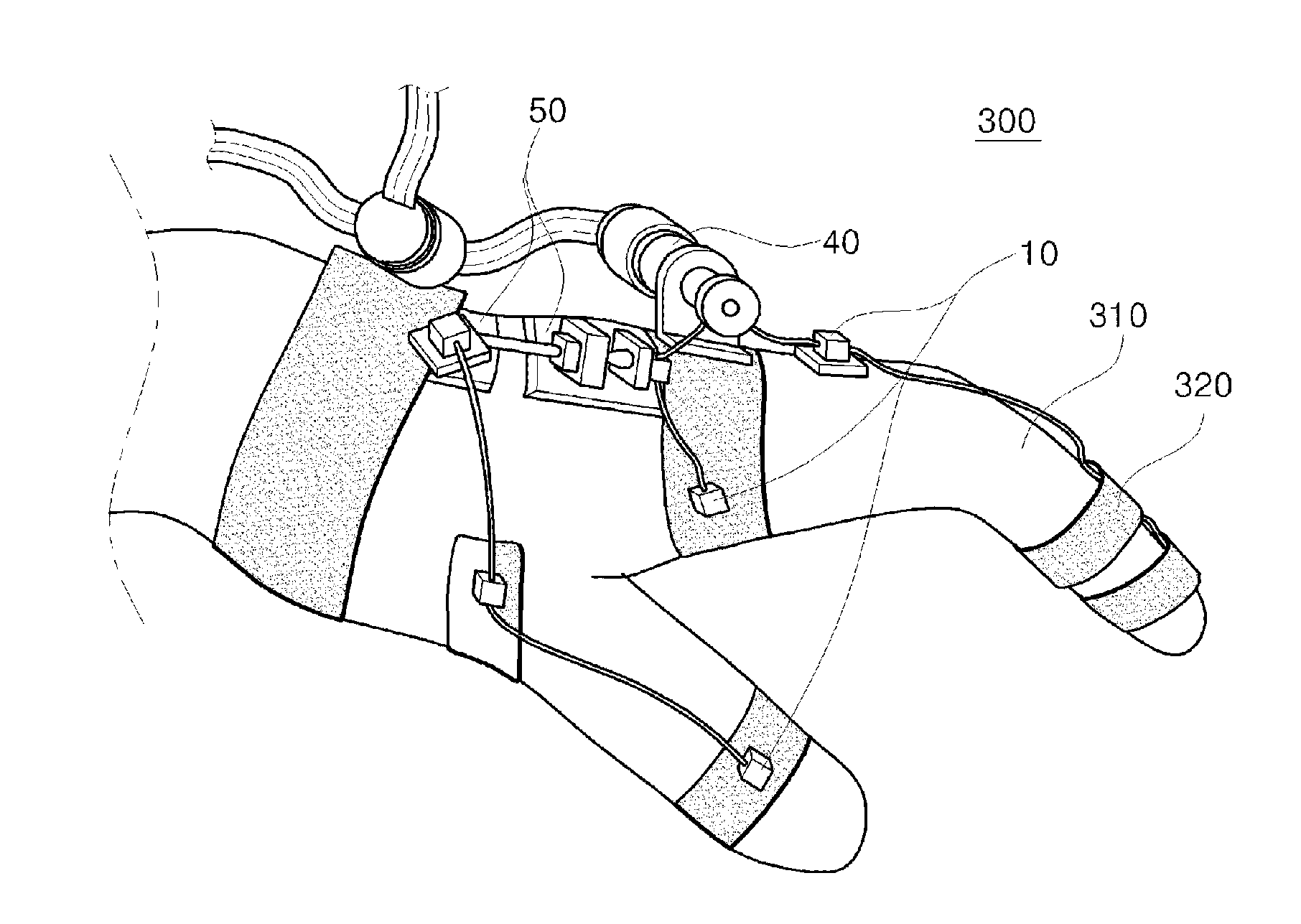
[0102]Referring to (a) of FIG. 13, a motion control device 300 of the third embodiment includes a guide 10 formed between the joint and the joint of the body, strings 20a, 20b connected along the guide, and a first motor 30 which is connected to the string and control the string to control a part of the body to move. For example, the guide 10 can be formed between the joint and the joint of the body, and in FIG. 12, the guide 10 is described as being formed between the node and the node of the hand.
[0103]The strings 20a, 20b are connected along the guide 10, and the two strings may be used depending on the embodiment. In an embodiment, the string connected along the guide formed in an interior region (palm) of the body is referred to as a first string 20a, and the string connected along the guide formed in an external region (back of the hand) of the body is referred to as a second string 20b.
[0104]The strings 20a, 20b can be formed of an elastic material or an inextensible materia...
PUM
 Abstract
Description
Claims
Application Information
 - R&D
- Intellectual Property
- Life Sciences
- Materials
- Tech Scout
- Unparalleled Data Quality
- Higher Quality Content
- 60% Fewer Hallucinations
Browse by: Latest US Patents, China's latest patents, Technical Efficacy Thesaurus, Application Domain, Technology Topic, Popular Technical Reports.
© 2025 PatSnap. All rights reserved.Legal|Privacy policy|Modern Slavery Act Transparency Statement|Sitemap|About US| Contact US: help@patsnap.com