Frangible and disintegrable tool and method of removing a tool

a tool and tool technology, applied in the field of subterranean drilling and completion, can solve the problems of undesirable presence and even deformation of tools, and achieve the effect of removing burden and less burden

Inactive Publication Date: 2015-07-09
BAKER HUGHES INC
View PDF33 Cites 5 Cited by
  • Summary
  • Abstract
  • Description
  • Claims
  • Application Information

AI Technical Summary

Benefits of technology

[0002]In the subterranean drilling and completion industry there are times when a downhole tool located within a wellbore becomes an unwanted obstruction. Accordingly, downhole tools have been developed that can be deformed, by operator action, for example, such that the tool's

Problems solved by technology

Although such tools work as intended, their presence

Method used


Image

  • Frangible and disintegrable tool and method of removing a tool
  • Frangible and disintegrable tool and method of removing a tool
  • Frangible and disintegrable tool and method of removing a tool

Examples


Embodiment Construction

[0010]A detailed description of one or more embodiments of the disclosed apparatus and method are presented herein by way of exemplification and not limitation with reference to the Figures.

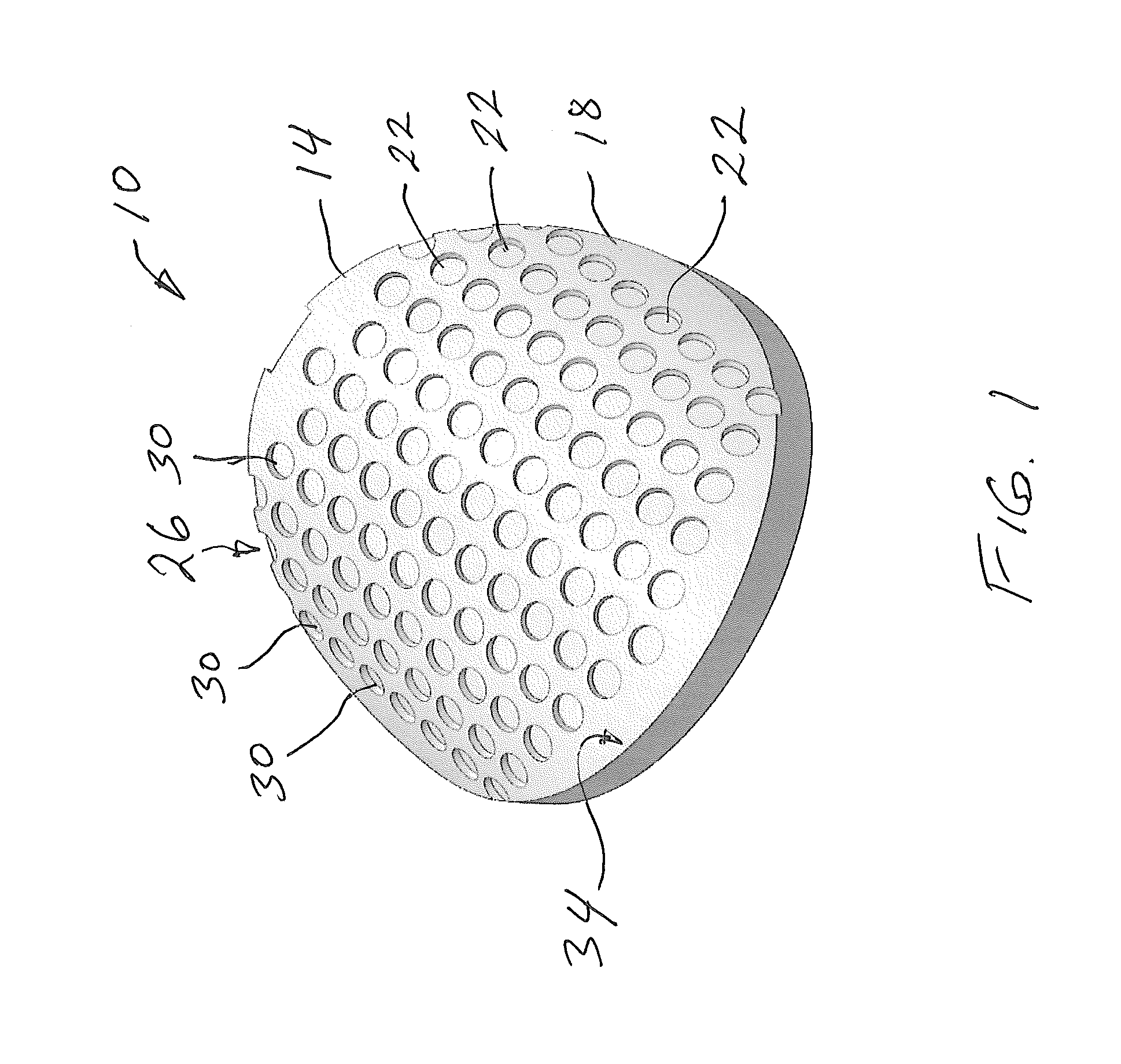
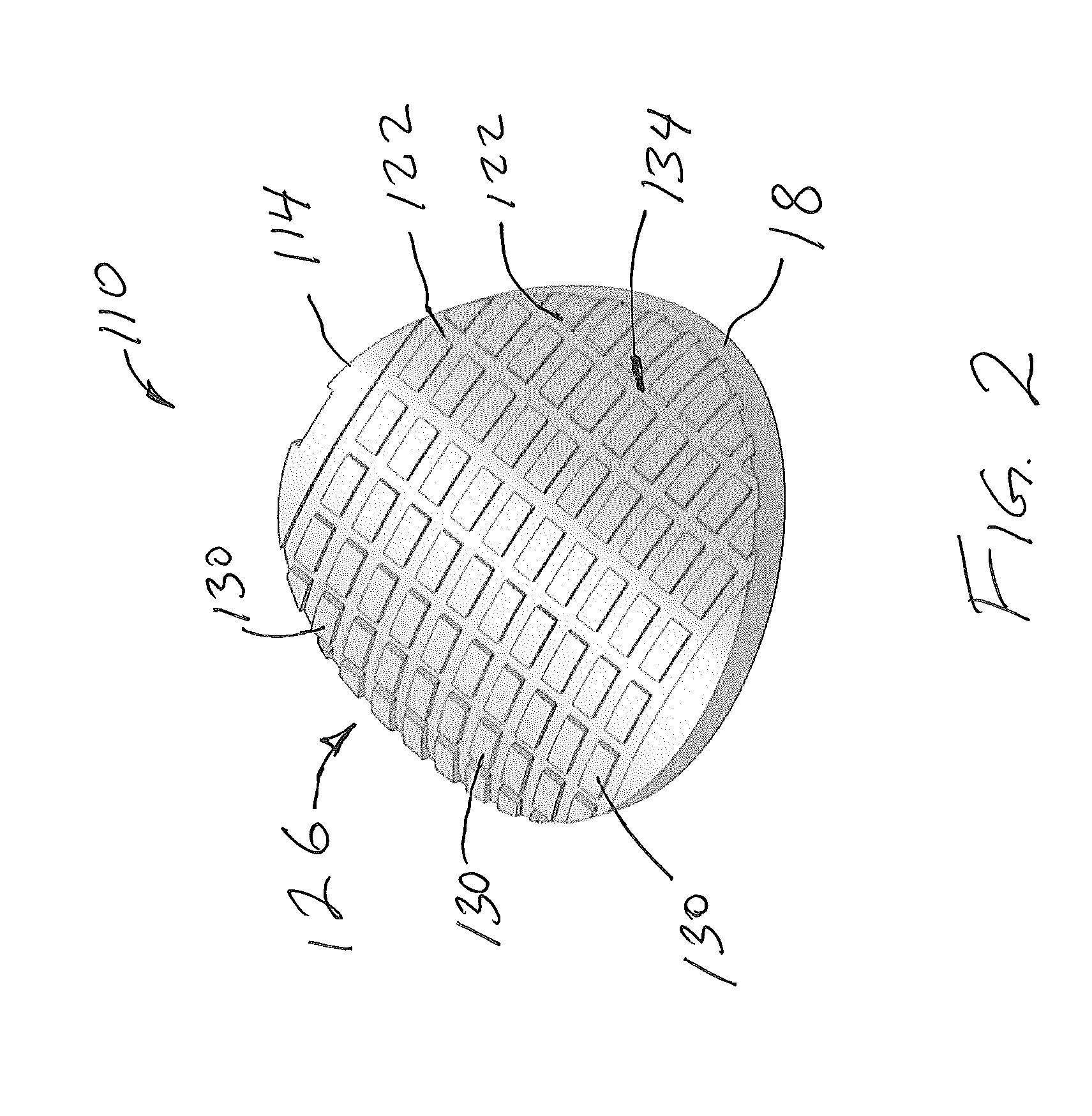
[0011]Referring to FIGS. 1 and 2 embodiments of frangible and disintegrable tools disclosed herein are illustrated at 10 and 110 respectively. The frangible and disintegrable tools 10, 110 include, a bodies 14, 114 made of a disintegrable material 18 having pluralities of stress risers 22, 122. The material 18 and the stress risers 22, 122 are configured such that when physically loaded to failure the bodies 14, 114 will break into a plurality of pieces of which a plurality will be of similar size.

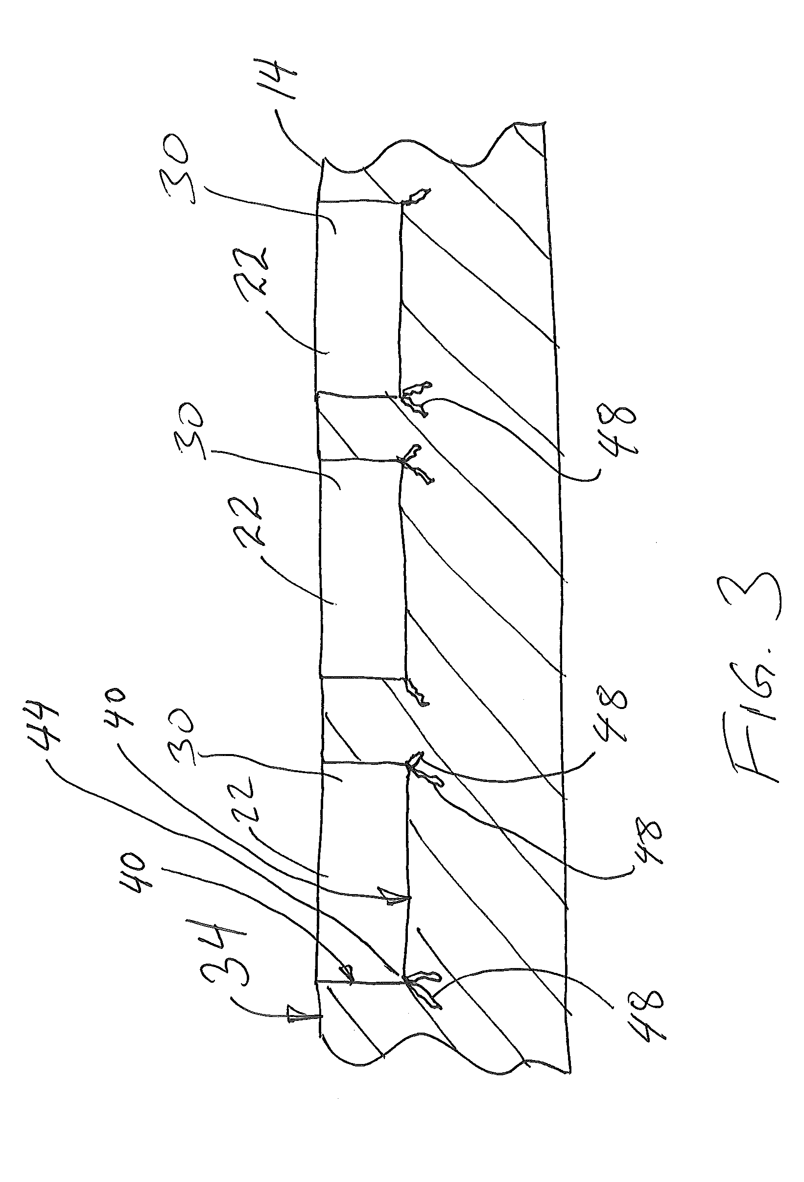
[0012]In the embodiment of FIG. 1, the stress risers 22 of the body 14 are defined by a repeating pattern 26 of recesses 30 that have cross sectional shapes that are ellipses recessed into a surface 34 of the body 14. The recesses 30 of the illustrated embodiment have circular cross sectional shapes; ho...


PUM


Abstract

A frangible and disintegrable tool includes, a body made of a disintegrable material having a plurality of stress risers, the disintegrable material and the plurality of stress risers are configured such that when physically loaded to failure the body will break into a plurality of pieces and a plurality of the plurality of pieces will be substantially similar in size.

Description

CROSS REFERENCE TO RELATED APPLICATIONS[0001]This application contains subject matter related to the subject matter of a co-pending application, which is assigned to the same assignee as this application, Baker Hughes Incorporated of Houston, Tex. and are both being filed on Jan. 9, 2014. The co-pending application is U.S. patent application Attorney Docket No. OMS4-56759 (BAO1178US) entitled DEGRADABLE METAL COMPOSITES, METHODS OF MANUFACTURE, AND USES THEREOF the entire contents of which are hereby incorporated by reference.BACKGROUND[0002]In the subterranean drilling and completion industry there are times when a downhole tool located within a wellbore becomes an unwanted obstruction. Accordingly, downhole tools have been developed that can be deformed, by operator action, for example, such that the tool's presence becomes less burdensome. Although such tools work as intended, their presence, even in a deformed state can still be undesirable. Devices and methods to further remove...

Claims


Application Information

Patent Timeline
IPC IPC(8): E21B29/00E21B34/06E21B33/12
CPCE21B29/00E21B34/06E21B33/12E21B33/1204
Inventor DENG, GUIJUNMA, GUOBINZHANG, ZHIHUIXU, ZHIYUE
Owner BAKER HUGHES INC
Why Eureka
Try Eureka