Input apparatus

a technology of input apparatus and input input, which is applied in the field of input apparatus, can solve the problems of operator stress, operator inability to obtain feedback to input, and operator inability to perceive whether the touch sensor detects the operation input, so as to eliminate the burden of re-inputting and the like for the operator.

Active Publication Date: 2012-06-21
KYOCERA CORP
View PDF55 Cites 40 Cited by
  • Summary
  • Abstract
  • Description
  • Claims
  • Application Information

AI Technical Summary

Benefits of technology

[0025]According to the present invention, when the position of the contact to the touch sensor moves into the predetermined region while the pressure load satisfies the standard load, the tactile sensation is provided to the object pressing the touch face. According to the present invention, therefore, it is possible to provide, through the touch sensor, the tactile sensation as it were a sensation obtained when operating the key and the like constituted of a mechanical switch. Thereby, it is possible for the operator to feel a realistic sensation, such as one obtained when operating a mechanical push-button switch, without a feeling of strangeness. In addition, since an operation based on an unintentional input by the operator is avoided, the burden of re-inputting and the like for the operator is eliminated.

Problems solved by technology

Since the touch sensors themselves are not physically displaced when touched, an operator cannot obtain feedback to an input even though the touch input is received.
As an operation feeling to “have pressed or have canceled pressing down” is not obtained in operation input, the operator cannot perceive whether the touch sensor detects the operation input.
As a result, the operator is likely to repeat inputting the same spot multiple times, which may be stressful for the operator.
However, such auditory feedback may be difficult to be confirmed in a noisy environment and is not applicable when the equipment being used is in a silent mode.
In addition, in using such visual feedback, if the input object displayed on the display unit is small, the operator may not be able to confirm the change in the display state, as a view of the input object is blocked by a finger, particularly when the operator is inputting by the finger.

Method used


Image

  • Input apparatus
  • Input apparatus
  • Input apparatus

Examples


Embodiment Construction

[0036]An embodiment of the present invention will be described with reference to the accompanying drawings.

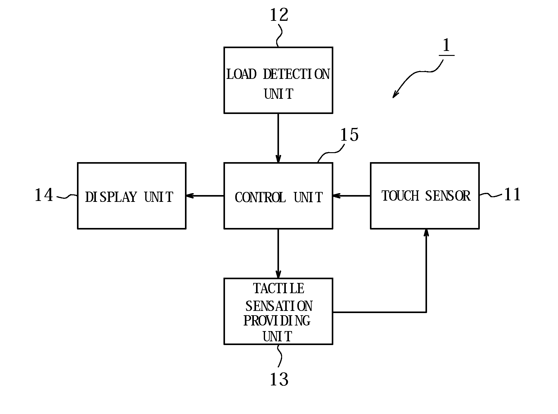
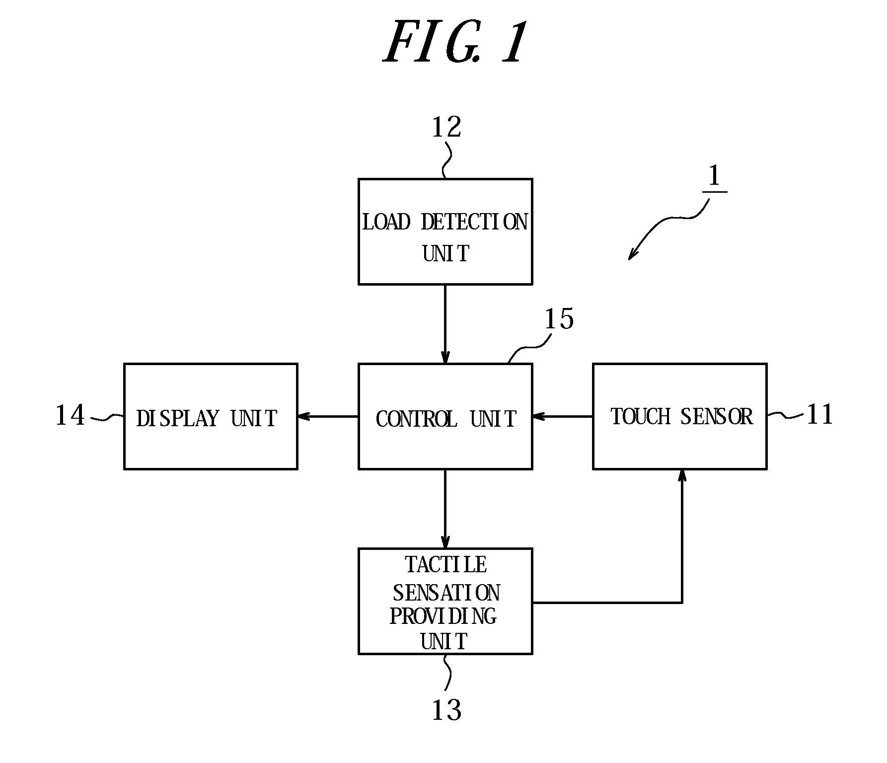
[0037]FIG. 1 is a block diagram illustrating a schematic constitution of an input apparatus according to an embodiment of the present invention. According to the present embodiment, any input apparatus is applicable, as long as it receives an operator's touch input by using a touch sensor. Such input apparatuses may be mounted on, for example, mobile terminals used to input characters and numbers, ATM machines at a bank, and ticket vending machines at a train station.

[0038]As illustrated in FIG. 1, an input apparatus 1 according to the present embodiment has a touch sensor 11, a load detection unit 12, a tactile sensation providing unit 13, a display unit 14, and a control unit 15 configured to control overall operations.

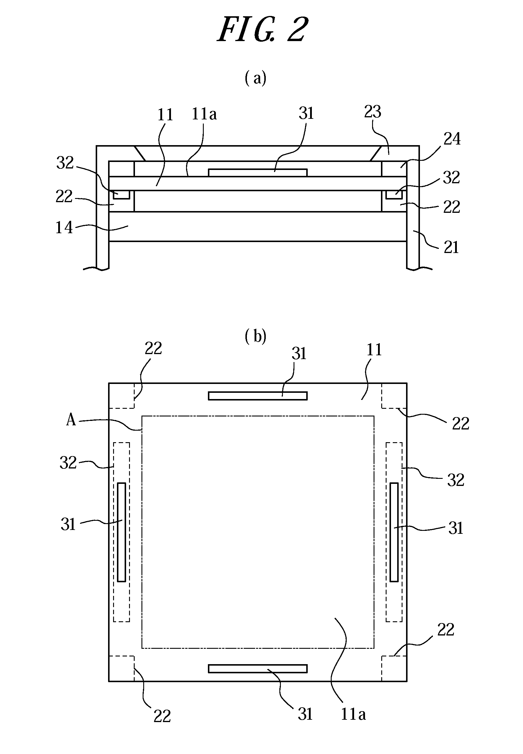
[0039]The touch sensor 11 is usually disposed on a front face of the display unit 14 such that a touch face of the touch sensor 11 detects a pressing input (co...


PUM


Abstract

An input apparatus capable of providing, through a touch sensor, a tactile sensation as it were a sensation obtained when operating a key and the like constituted of a mechanical switch.An input apparatus 1 has a touch sensor 11 configured to detect a contact, a load detection unit 12 configured to detect a pressure load on a touch face of the touch sensor 11, a tactile sensation providing unit 13 configured to vibrate the touch face, and a control unit 15 configured to control drive of the tactile sensation providing unit 13, when a position of the contact detected by the touch sensor 11 moves into a predetermined region while the pressure load detected by the load detection unit 12 satisfies a predetermined standard, such that a tactile sensation is provided to an object pressing the touch face.

Description

CROSS REFERENCE TO RELATED APPLICATION[0001]This application claims priority to and the benefit of Japanese Patent Application No. 2009-197318 filed on Aug. 27, 2009, the entire contents of which are incorporated herein by reference.TECHNICAL FIELD[0002]The present invention relates to an input apparatus having a touch sensor.BACKGROUND ART[0003]In recent years, there are mobile terminals such as mobile phones that employ input apparatuses having touch sensors such as touch panels, touch switches, or the like, as input apparatuses such as operation units, switches and the like configured to receive input operations by users. Such input apparatuses having touch sensors are popularly employed not only by the mobile terminals but also by information equipments such as calculators, ticket vending machines, home electric appliances such as microwaves, TV sets, lighting equipments, industrial equipments (FA equipments) and the like.[0004]There are known a variety of types of those touch s...

Claims


Application Information

Patent Timeline
Patent Type & Authority Applications(United States)
IPC IPC(8): G06F3/041
CPCG06F3/016G06F3/0416G06F3/0414G06F3/04142
Inventor KONO, KENJI
Owner KYOCERA CORP
Why Eureka
Try Eureka