
Vehicle windshield wiper for rain and snow dual purpose

a dual-purpose, vehicle technology, applied in vehicle maintenance, vehicle cleaning, domestic applications, etc., can solve the problems of increasing fuel expense, unable to achieve promotion effect, and serious affecting driving safety, so as to save extra expense, reduce gas consumption and fuel expense, and eliminate pollution burden

Inactive Publication Date: 2008-09-18
HUANG SHIH HSIEN
View PDF11 Cites 41 Cited by
  • Summary
  • Abstract
  • Description
  • Claims
  • Application Information

AI Technical Summary

Benefits of technology

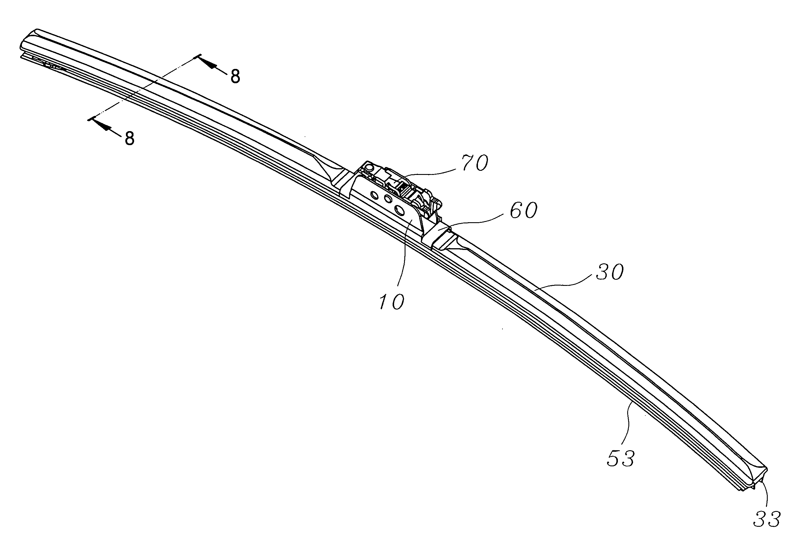
"The present invention provides a vehicle windshield wiper for rain and snow dual purpose. It includes a bow elastic strip, clamping devices, a strip scraper receptacle, a sheath cover, a strip scraper, two end ferrule caps, and a truss saddle. The bow elastic strip replaces the holding supports in the conventional arm-supported snow wiper and is enveloped by the sheath cover and ferrule caps to prevent snow and ice particles from entering any space. This eliminates the need for a separate snow wiper and reduces the pollution burden. The wiper is also lighter and smaller than conventional snow wipers, resulting in less gas consumption and lower fuel expense for vehicles. It has a simple structure and easy production, saving manufacturing costs and benefiting consumers."

Problems solved by technology

If the replacement of the wiper does not take action in time, the conventional arm-supported wiper W will become stiff and losing elasticity due to the attachment and gathering of the snow and icy particles in the master wiper support and the other holding supports and result in seriously affecting the driving safety in consequence of losing function of scraping snow on the windshield.
This unfair marketing status, the consumers are the losers and the vendors and manufacturers are the winners, always exists in the snow area so far.
For some other snow wipers in prior art such as US patent numbers of U.S. Pat. Nos. 5,412,177, 5,603,856, 6,049,939, 5,784,751 and the like are different from the foregoing snow wiper of external cover, they all have additional thermal apparatus contrivance to melt the snow on the wiper by heating energy; Therefore, all such kind of snow wipers will increase the fuel expense due to extra gas consumption by the additional thermal apparatus.
Moreover, in order to have such additional thermal apparatus installed in the engine compartment of limited space, not only the initial adaptation cost is considerable but also the routine maintenance fee is much; Hence, it does not appeal the consumers due to high total cost thereof and result in failing in the mainstream market without promotional effect.
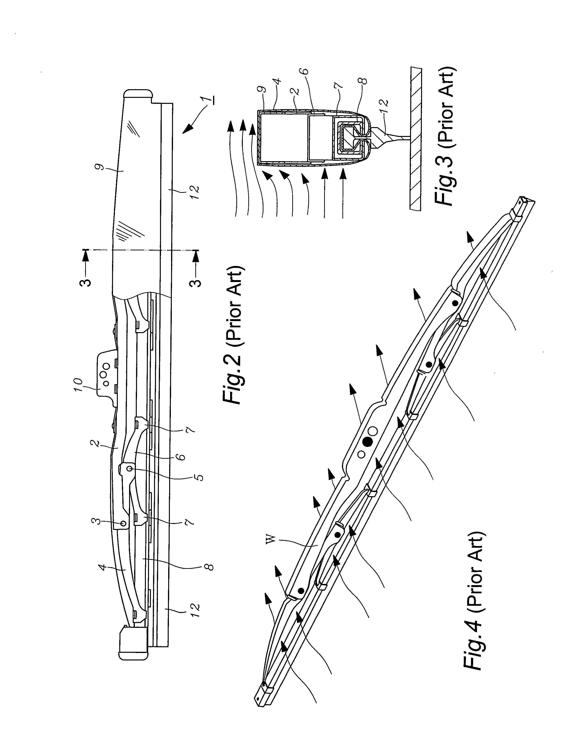
(1). as shown in the FIGS. 3 and 5, although the external cover 9 wrapping on the conventional arm-supported snow wiper 1 can separate and block the intrusion of the snow and icy particles, but the long side of which will become a wind flow barrier during vehicle moving against the wind current so that the motor M, which transmits driving power to the wiper via wiper arm R and wiper arm linking bar S, will suffer a counter reaction from said external cover 9, which will lead to the increase of power output from motor M and indirectly cause the increase automobile fuel and oil costs; Contrarily, as shown in the FIGS. 4 and 5, during not winter snow season, using the conventional arm-supported wiper W, the wind flow can pass through the gaps among all arms, which means it bears less counter reaction relatively and the motor M outputs less power relatively as well as vehicle fuel will be more economical; In other words, the conventional arm-supported snow wiper 1 does more than conventional arm-supported wiper W fuel consumption; In particular, the accumulation throughout the winter snow season will be more obvious, whereas, the vehicle consuming drivers are still forced to accept it.

Method used


Image

  • Vehicle windshield wiper for rain and snow dual purpose
  • Vehicle windshield wiper for rain and snow dual purpose
  • Vehicle windshield wiper for rain and snow dual purpose

Examples


Embodiment Construction

[0030]Prior to the description of the concrete embodiment for the present invention, it is declared that the present invention is developed from refining the drawbacks of the conventional arm-supported snow wiper together with the previous product of no-holding-support windshield wiper, which is invented by the same inventor and has being granted the U.S. Pat. No. 7,150,066, Japanese patent No. 3115053 and Taiwan patent No. M27955 respectively. The structure of such wiper is shown as in FIG. 6 to FIG. 8, which comprises:

[0031]a truss saddle 10 is to be fixed at the end of the wiper arm R by means of the wiper jointer 70;

[0032]a bow elastic stripe 20, which being made by metal stripe bow downwards, is securely jointed with the base side of said truss saddle 10 central upper side thereat; Some polygon holes 21 are evenly punched on the surface; Some oblong hollow pressure adjusting vents 22 are perforated between said adjacent polygon holes 21 with adequate aperture size for even stre...


PUM


Abstract

The present invention is to provide a “vehicle windshield wiper for rain and snow dual purpose”, which comprises a bow elastic strip, some clamping devices, a strip scraper receptacle, a sheath cover, a strip scraper, two end ferrule caps and a truss saddle; Wherein, the sheath cover and two end ferrule caps totally envelope the bow elastic strip, clamping devices and strip scraper receptacle so that the snow and icy particles are blocked and separated out unable to intrude or gather in any space thereof; Thereby, the dual function of rain wiper and snow wiper of present invention eliminates the boring action in swapping between rain wiper and snow wiper during interim of snow and non-snow seasons so that it not only saves the extra expense in buying snow wiper for the consuming vehicle drivers but also totally obsoletes the conventional arm-supported snow wiper so as to eliminate the pollution burden incurred by the mass waste conventional snow wipers; Thus, it really possesses double effect in economic benefit and environmental protection.

Description

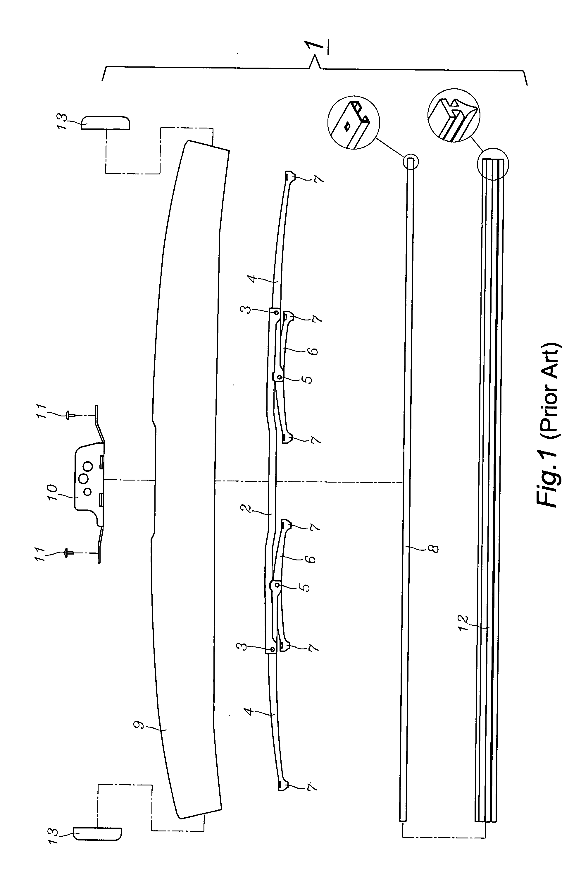
FIELD OF THE PRESENT INVENTION[0001]The present invention relates to a “vehicle windshield wiper for rain and snow dual purpose”, which can be universally used under any weather so that not only the swap between rain wiper and snow wiper is avoided but also the bearing area against wind flow is tremendously reduced and results in less fuel consumption due to decrease in output power of the wiper-driving motor so as to achieve double effect in economic benefit and environmental production.BACKGROUND OF THE INVENTION[0002]Currently, most of the structure in the windshield snow wiper for the vehicle is adapted from the conventional arm-supported wiper by wrapping a layer of external cover and inserting a strip scraper at the bottom side thereof. As shown in the FIG. 1 to FIG. 5, the conventional arm-supported snow wiper 1 comprises a master wiper support 2, a first holding support 4, a second holding support 6, an elastic strip scraper receptacle 8, a hollow tubular external cover 9, a...

Claims


Application Information

Patent Timeline
Patent Type & Authority Applications(United States)
IPC IPC(8): B60S1/32
CPCB60S1/3806B60S1/381B60S1/3851B60S2001/3843B60S1/3887B60S1/3894B60S1/524B60S1/3881
Inventor HUANG, SHIH-HSIEN
Owner HUANG SHIH HSIEN
Learn More