Generating a low-latency transparency effect

a transparency effect and low-latency technology, applied in the field of graphics processing, can solve the problems of obstructing the user's field of view, interfering with the user's ability, and affecting the user's ability to navigate his or her surroundings, and achieve the effect of transparent effect and efficient viewing of information on the display devi

Inactive Publication Date: 2015-07-09
NVIDIA CORP
View PDF4 Cites 129 Cited by
  • Summary
  • Abstract
  • Description
  • Claims
  • Application Information

AI Technical Summary

Benefits of technology

[0010]Advantageously, the disclosed technique enables a display device to be configured to simulate a transparency effect in real-time. Additionally, the disclosed technique enables the transparency effect to be modified based on changes to the point of view of the user relative to the display device to provide the user with a continuous line of sight through the display device. Accordingly, the user is able to more efficiently view information on the display device while also viewing and interacting with objects that would otherwise be obscured by the display device.

Problems solved by technology

However, a large display may obstruct a user's field of view, interfering with the user's ability to effectively interact and communicate with others or pay attention to the surrounding environment while viewing information on the larger display.
Additionally, in mobile display applications, obstructing a user's field of view with a display device may interfere with the user's ability to navigate his or her surroundings.
As a result, viewing a mobile display device while walking may result in injury to the user or to those nearby the user.
Unfortunately, the transparent electronic devices depicted in conceptual product designs generally are based on technologies and materials that are not yet commercially available and / or which do not yet exist.
However, conventional electronic devices typically exhibit a significant amount of latency associated with processing and displaying images captured by the rear-facing camera.
This latency may significantly detract from the user experience when an end-user is attempting to interact with his or her surroundings in real-time.

Method used


Image

  • Generating a low-latency transparency effect
  • Generating a low-latency transparency effect
  • Generating a low-latency transparency effect

Examples


Embodiment Construction

[0018]In the following description, numerous specific details are set forth to provide a more thorough understanding of the present invention. However, it will be apparent to one of skill in the art that the present invention may be practiced without one or more of these specific details.

System Overview

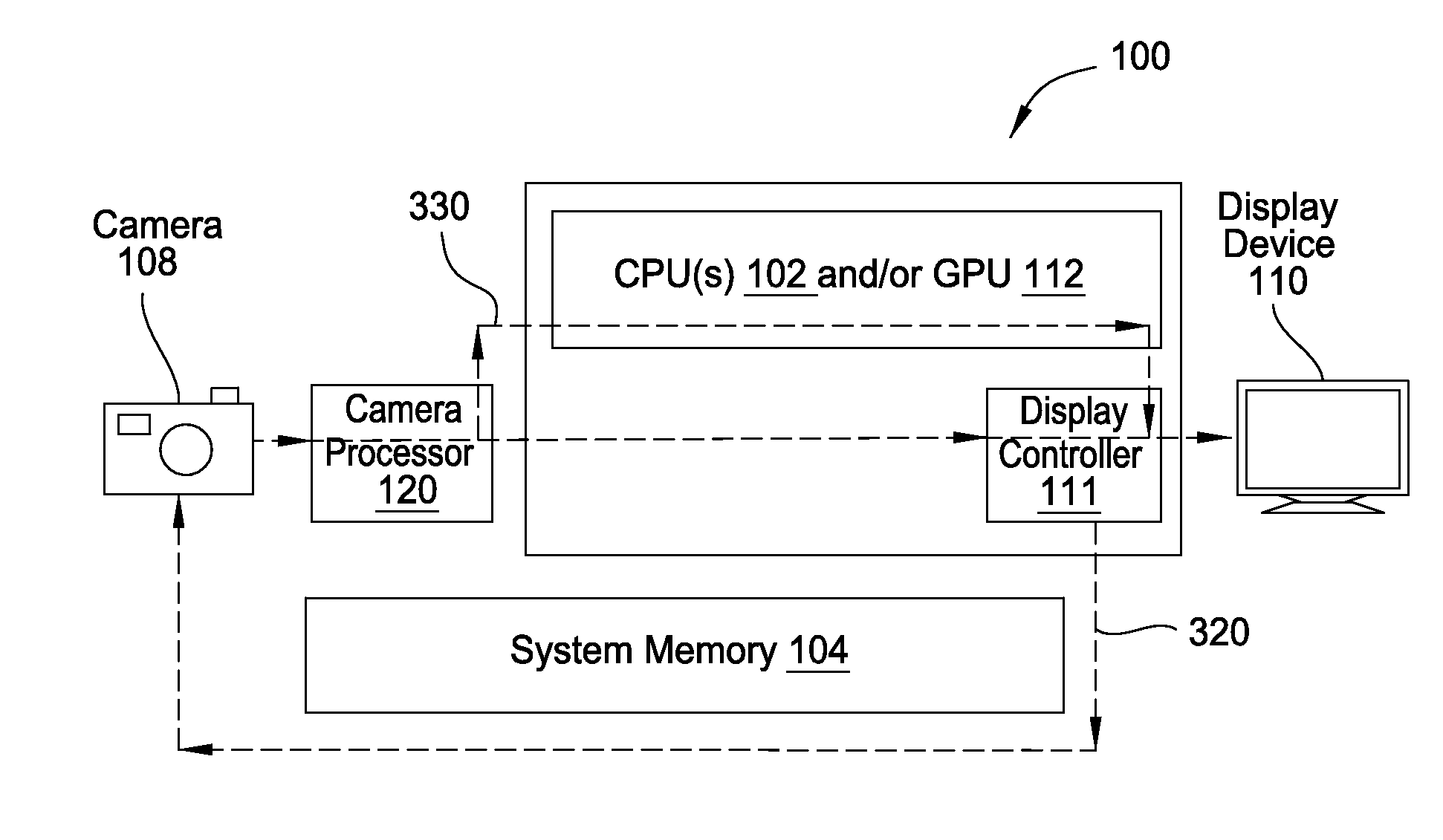
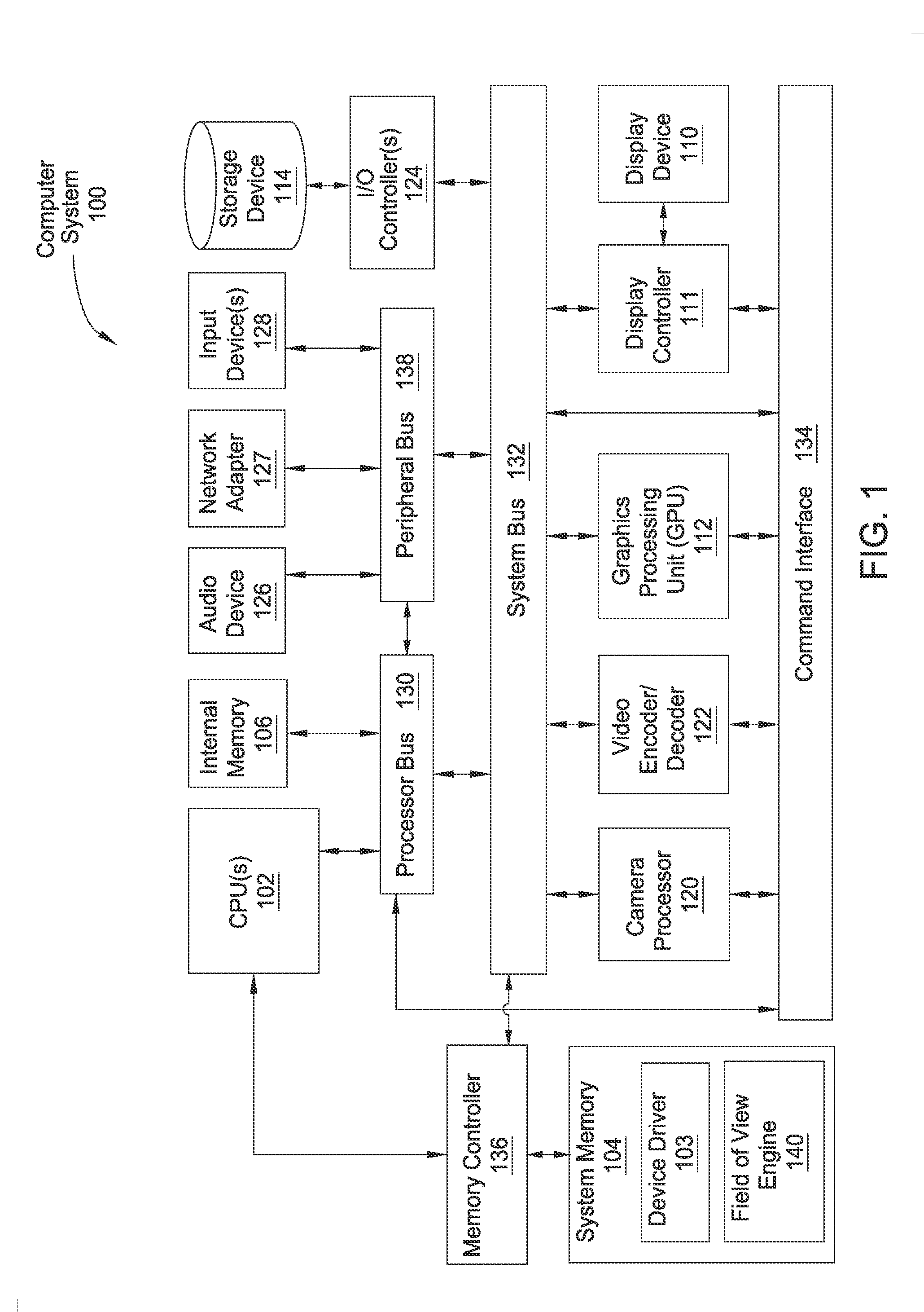
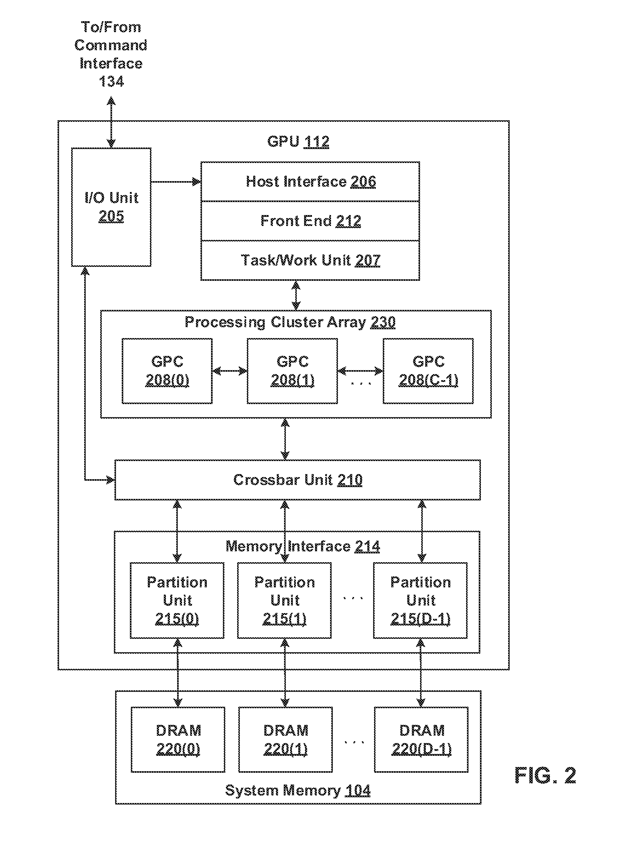
[0019]FIG. 1 is a block diagram illustrating a computer system 100 configured to implement one or more aspects of the present invention. As shown, computer system 100 includes, without limitation, one or more central processing units (CPUs) 102 coupled to a system memory 104 via a memory controller 136. The CPU(s) 102 may further be coupled to internal memory 106 via a processor bus 130. The internal memory 106 may include internal read-only memory (IROM) and / or internal random access memory (IRAM). Computer system 100 further includes a processor bus 130, a system bus 132, a command interface 134, and a peripheral bus 138. System bus 132 is coupled to a camera processor 120, video en...


PUM


Abstract

One embodiment of the present invention sets forth a technique for generating a transparency effect for a computing device. The technique includes transmitting, to a camera, a synchronization signal associated with a refresh rate of a display. The technique further includes determining a line of sight of a user relative to the display, acquiring a first image based on the synchronization signal, and processing the first image based on the line of sight of the user to generate a first processed image. Finally, the technique includes compositing first visual information and the first processed image to generate a first composited image, and displaying the first composited image on the display.

Description

BACKGROUND OF THE INVENTION[0001]1. Field of the Invention[0002]Embodiments of the present invention generally relate to graphics processing and, more specifically, to generating a low-latency transparency effect.[0003]2. Description of the Related Art[0004]Display devices are widely used in a variety of electronic systems to provide visual information to a user. For example, a display device may be used to provide a visual interface to the user of a desktop computer. In addition, advancements in display technologies have enabled display devices to be incorporated into a number of mobile applications, such as laptop computers, tablet computers, and mobile phones. In such applications, display devices are capable of providing high-resolution interfaces that are capable of accurately reproducing a wide color gamut.[0005]Electronic systems having larger displays generally provide a more immersive user-experience. However, a large display may obstruct a user's field of view, interfering...

Claims


Application Information

Patent Timeline
Patent Type & Authority Applications(United States)
IPC IPC(8): G09G5/12G06T19/00G06T1/00G06T5/50G06T11/00H04N5/235
CPCG09G5/12G06T11/001H04N5/2352G06T1/0007G06T5/50G06T2210/62G09G2340/12G09G2340/14G06T2215/16G06T2200/28G06T19/006G06T11/00G09G5/36G09G2340/0407G09G2340/10G09G2340/125G09G2350/00G09G2354/00H04N23/661H04N23/61H04N23/63H04N23/73
Inventor HICOK, GARY D.
Owner NVIDIA CORP
Why Eureka
Try Eureka