Multi-sector radar
a multi-sector radar and radar technology, applied in the field of multi-sector radars, can solve the problems of phase rotation, correlation characteristic of reception signals deterioration, and does not consider the operation of multi-sector radars when phase rotation is carried out, so as to suppress interference and suppress correlation characteristics of reception signals.
- Summary
- Abstract
- Description
- Claims
- Application Information
AI Technical Summary
Benefits of technology
Problems solved by technology
Method used
Image

Examples
first embodiment
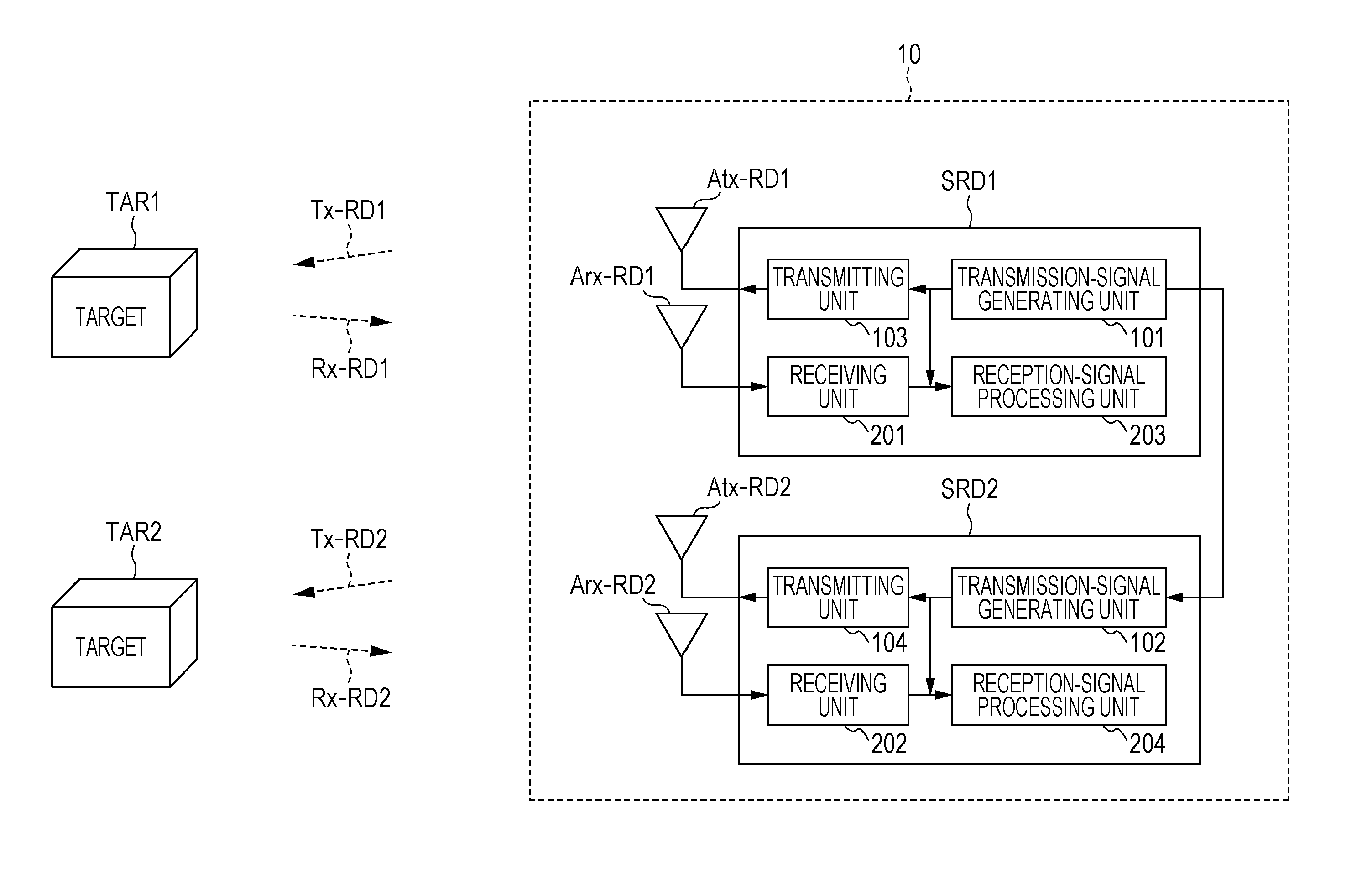
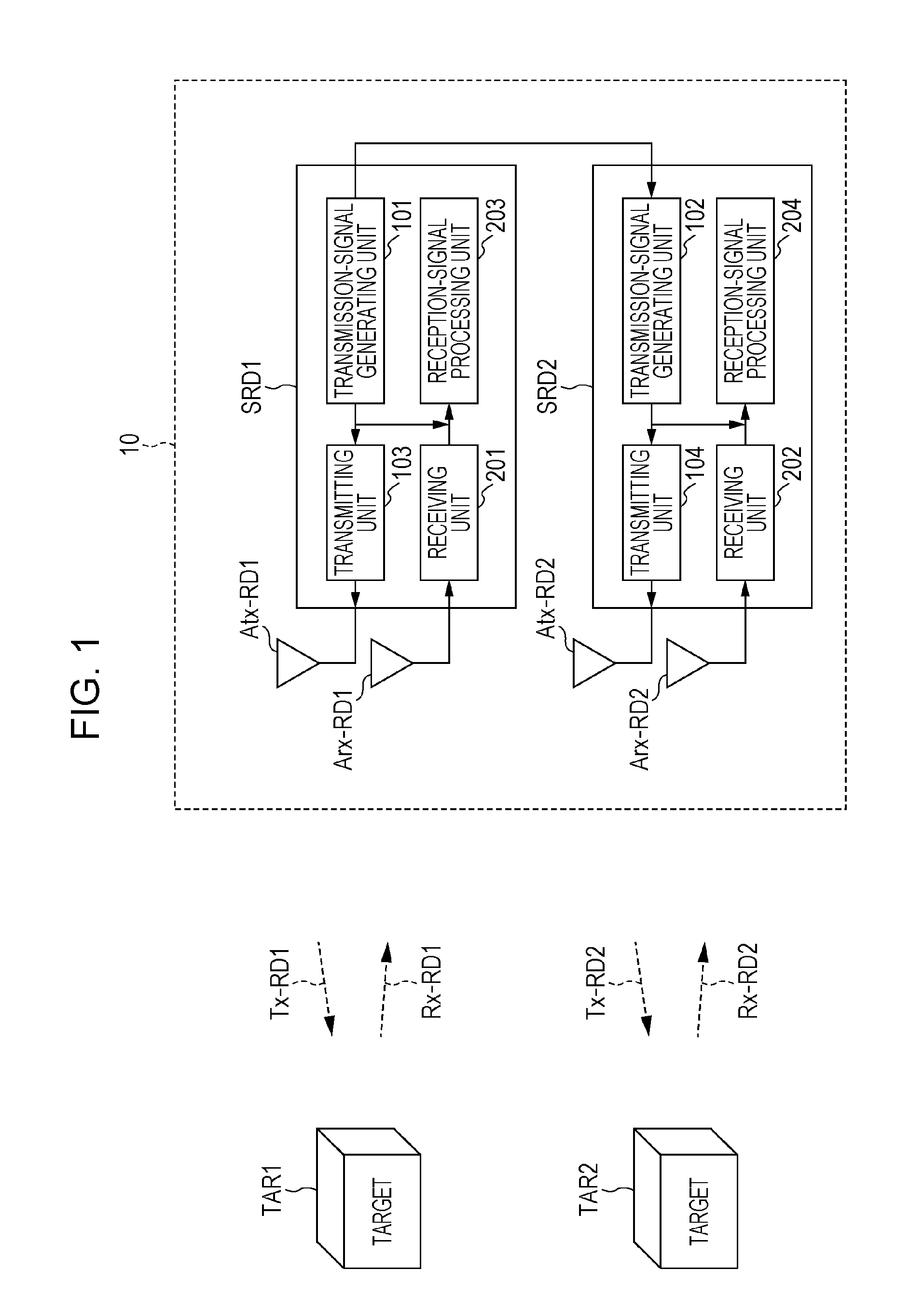
[0026]First, the basic configuration of a multi-sector radar 10 in the present embodiment will be described with reference to FIG. 1. FIG. 1 is a block diagram illustrating the basic configuration of the multi-sector radar 10 in embodiments described herein. The multi-sector radar 10 illustrated in FIG. 1 includes a plurality of (e.g., two) sector radars SRD1 and SRD2 and detects the presence / absence of targets TAR1 and TAR2 (e.g., automobiles or people in a wide angular range). The two sector radars SRD1 and SRD2 have the same or similar configurations. Thus, in the embodiments described below, the operations of units in the sector radar SRD1 are described in detail, and the operations of units in the sector radar SRD2 are also described, as needed.
[0027]The sector radar SRD1 includes a transmission-signal generating unit 101, a transmitting unit 103 to which a transmission antenna Atx-RD1 is connected, a receiving unit 201 to which a reception antenna Arx-RD1 is connected, and a r...
second embodiment
[0123]It is preferable that the multi-sector radar 10 use Spano codes as transmission code sequences in order to achieve a more superior sidelobe suppression characteristic than the suppression characteristic of sidelobes in the coherent addition results in the coherent addition units 341 and 342.
[0124]In a second embodiment, a description will be given of an example of the multi-sector radar 10 using Spano codes for the transmission code sequences. Of the operations of the multi-sector radar 10 in the present embodiment, the same details as those of the operation of the multi-sector radar 10 in the first embodiment are not described or are briefly described, and different details will be described.
[0125]Spano codes are code sequences including code sequences A and B that constitute complementary code sequences (A and B) and reversed-order code sequences A′ and B′ of the code sequences A and B. Compared with the multi-sector radar using complementary codes, a multi-sector radar usin...
third embodiment
[0198]In the second embodiment described above, using eight code sequences, which are a Spano code set, as a unit, each sector radar SRD1 or SRD2 in the multi-sector radar 10 repeatedly multiplies the eight code sequences by the corresponding orthogonalized code V1 or V2, each having a vector length of 4, four times.
[0199]In a third embodiment, the sector radars SRD1 and SRD2 in the multi-sector radar 10 repeatedly use eight code sequences 2N (=N+N) times and further use the orthogonalized codes V1 and V2, each having a vector length of N, and an inter-range-interference-suppressing code OC (={1, −1, 1, −1, 1, −1, 1, −1}). The inter-range-interference-suppressing code OC is a code in which {+1} and {−1} are alternately repeated and is a vector having a length of 8.
[0200]In the present embodiment, there are two methods for multiplying the orthogonalized codes V1 and V2, the inter-range-interference-suppressing code OC, and eight code sequences, which are a Spano code set, as in the s...
PUM
 Abstract
Description
Claims
Application Information