Sub-resolution optical detection

a sub-resolution, optical detection technology, applied in the direction of mechanical pattern conversion, reradiation, instruments, etc., can solve the problems of increasing costs, limiting the resolution of digital image processing systems, and complicating the resolution issue through active illumination, so as to achieve more accurate mapping

a sub-resolution, optical detection technology, applied in the direction of mechanical pattern conversion, reradiation, instruments, etc., can solve the problems of increasing costs, limiting the resolution of digital image processing systems, and complicating the resolution issue through active illumination, so as to achieve more accurate mapping

US20150198716A1Active Publication Date: 2015-07-16META PLATFORMS TECH LLC

Image

  • Sub-resolution optical detection
  • Sub-resolution optical detection
  • Sub-resolution optical detection

Examples


Embodiment Construction

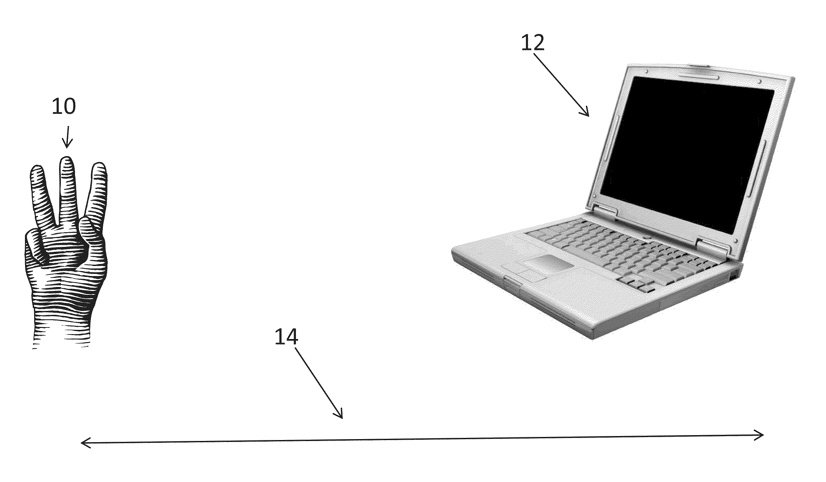
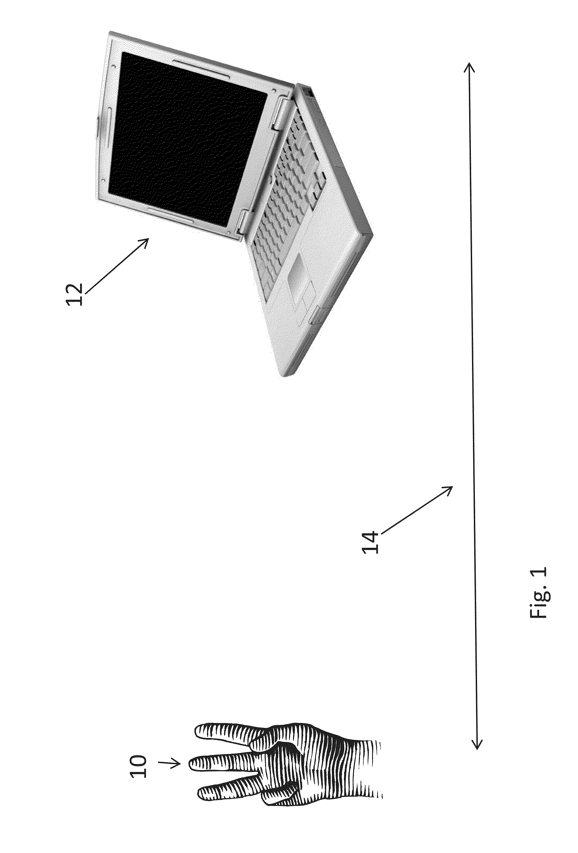
[0052]As explained above, the present invention, in some embodiments thereof, relates to apparatus and a method for sub-resolution optical detection and, more particularly, but not exclusively, to such apparatus and a method for detection in a three-dimensional space of user interactions for operating digital equipment.

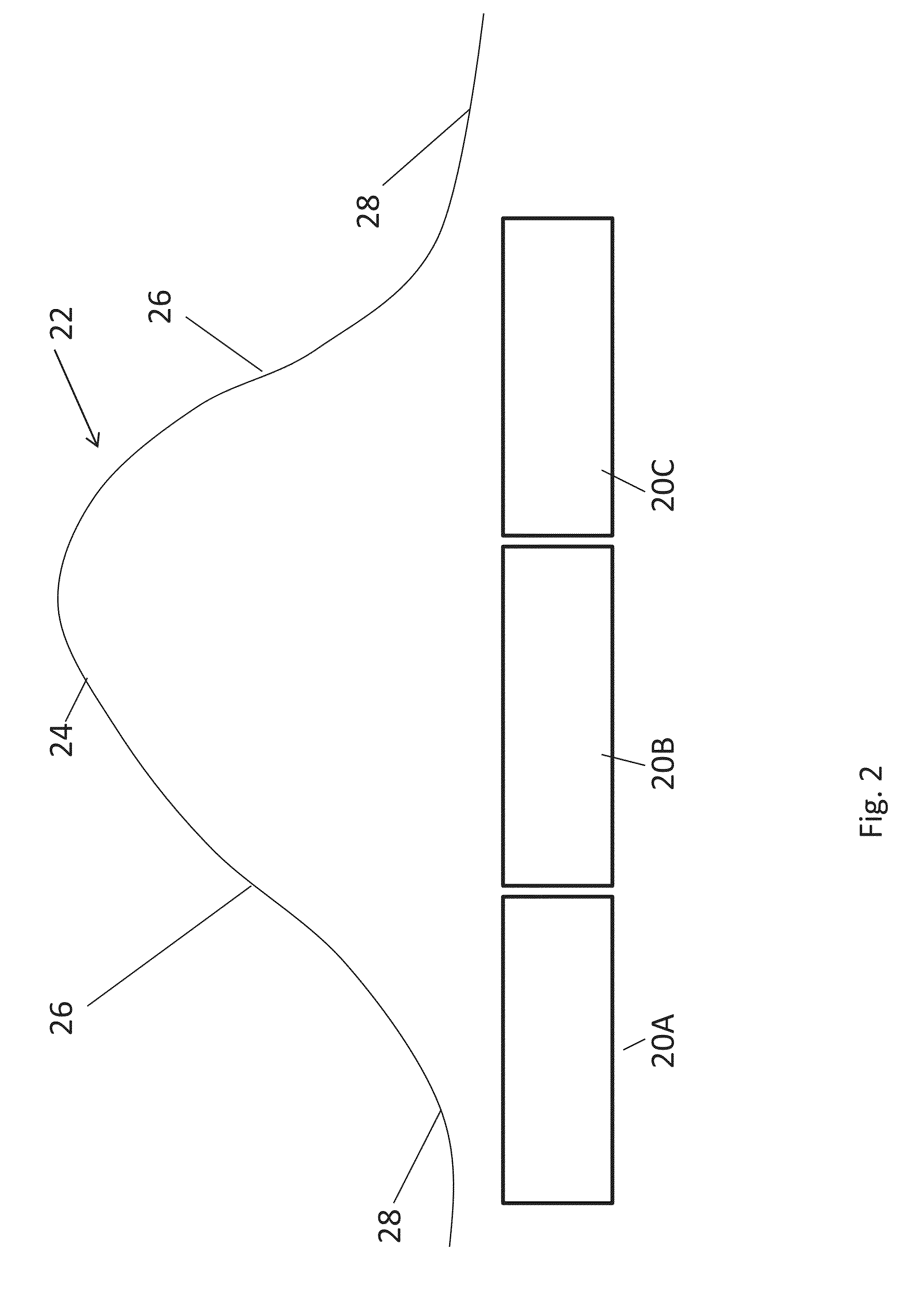
[0053]In one embodiment a volume is actively illuminated by light beams. The light beams may be structured, for example in the form of parallel lines or spots or a grid or a combination of the above, and the beams may be produced by lasers. Individual beams as reflected from objects in the volume do not produce clear features but rather produce a smeared line or a smeared spot where the brightness has a distribution around the center, typically a Gaussian distribution. The peak part of the Gaussian may often be smaller than the size of the individual detecting pixel although the overall Gaussian distribution can be larger. The distribution of the brightness over sever...


PUM


Abstract

A detector for optical detection of location within a volume, comprises a beam source for shining a structured light pattern on the volume and a digital detector having detection pixels of a given size. The light pattern, when shone into the volume and reflected back to the detection pixels, has a brightness distribution with a peak and a surrounding brightness structure. Now often the peak may be smaller than the pixel size although the overall distribution of the brightness extends over multiple pixels. The system includes an electronic processor for assessing a distribution of brightness among the neighbouring pixels to infer a location of the peak within a region smaller than the size of the central pixel on which it falls, thus giving sub-pixel resolution.

Description

RELATED APPLICATION[0001]This application claims the benefit of priority under 35 USC 119(e) of U.S. Provisional Patent Application No. 61 / 926,476 filed Jan. 13, 2014, the contents of which are incorporated herein by reference in their entirety.FIELD AND BACKGROUND OF THE INVENTION[0002]The present invention, in some embodiments thereof, relates to apparatus and a method for sub-resolution optical detection and, more particularly, but not exclusively, to such apparatus and a method for detection in a three-dimensional space of user interactions for operating digital equipment.[0003]In digital image processing, sub-pixel resolution can be obtained in digital images containing well defined lines, points or edges that can be processed by an algorithm to reliably measure the position of the line, point or edge in the image with an accuracy exceeding the nominal pixel resolution of that image.[0004]Thus, for example, if the image of a car of length 50 cm, viewed side-on is 500 pixels lon...

Claims


Application Information

Patent Timeline
16 Jul 2015
Publication
US20150198716A1
IPC
G01S17/06; G01S7/48; G06F3/01; G01S17/89
CPC
G01S17/06; G01S7/48; G06F3/017; G01S17/48; G01S17/89; G06F3/011; G06F3/0304; G01S7/481
Inventors
ROMANO, NITAY; GROSSINGER, NADAV