Digital protection relay, digital protection relay test device, and digital protection relay test method

a digital protection relay and test device technology, applied in emergency protection circuit arrangements, emergency protection arrangements for limiting excess voltage/current, etc., can solve the problems of small power outage of the main circuit, inability to protect the main circuit, and limited time for conducting digital protection relay test. , to achieve the effect of safe and easy operation tes

Inactive Publication Date: 2015-07-16
KK TOSHIBA
View PDF5 Cites 10 Cited by
  • Summary
  • Abstract
  • Description
  • Claims
  • Application Information

AI Technical Summary

Benefits of technology

The technical effect of this patent is that it provides a way for testing digital protective relays safely and easily without having to turn off the main circuit first. This makes maintenance or repair more efficient and reliable.

Problems solved by technology

The technical problem addressed by this patent relates to limitations placed on testing digital protective relays due to constraints related to the design of conventional test devices and procedures. These restrictions include the requirement for a high-current/voltage generator, the inconvenience of opening and closing panels containing the test terminals, and the risk of failing to protect the main circuit should a failure occur during testing. This results in limited opportunities for testing and significant impact on operation efficiency.

Method used


Image

  • Digital protection relay, digital protection relay test device, and digital protection relay test method
  • Digital protection relay, digital protection relay test device, and digital protection relay test method
  • Digital protection relay, digital protection relay test device, and digital protection relay test method

Examples


Embodiment Construction

[0015]Hereinafter, an embodiment will be described with reference to the drawings.

[0016]The present embodiment enables an operational test of a digital protection relay while continuing protection of a main circuit without powering off the main circuit.

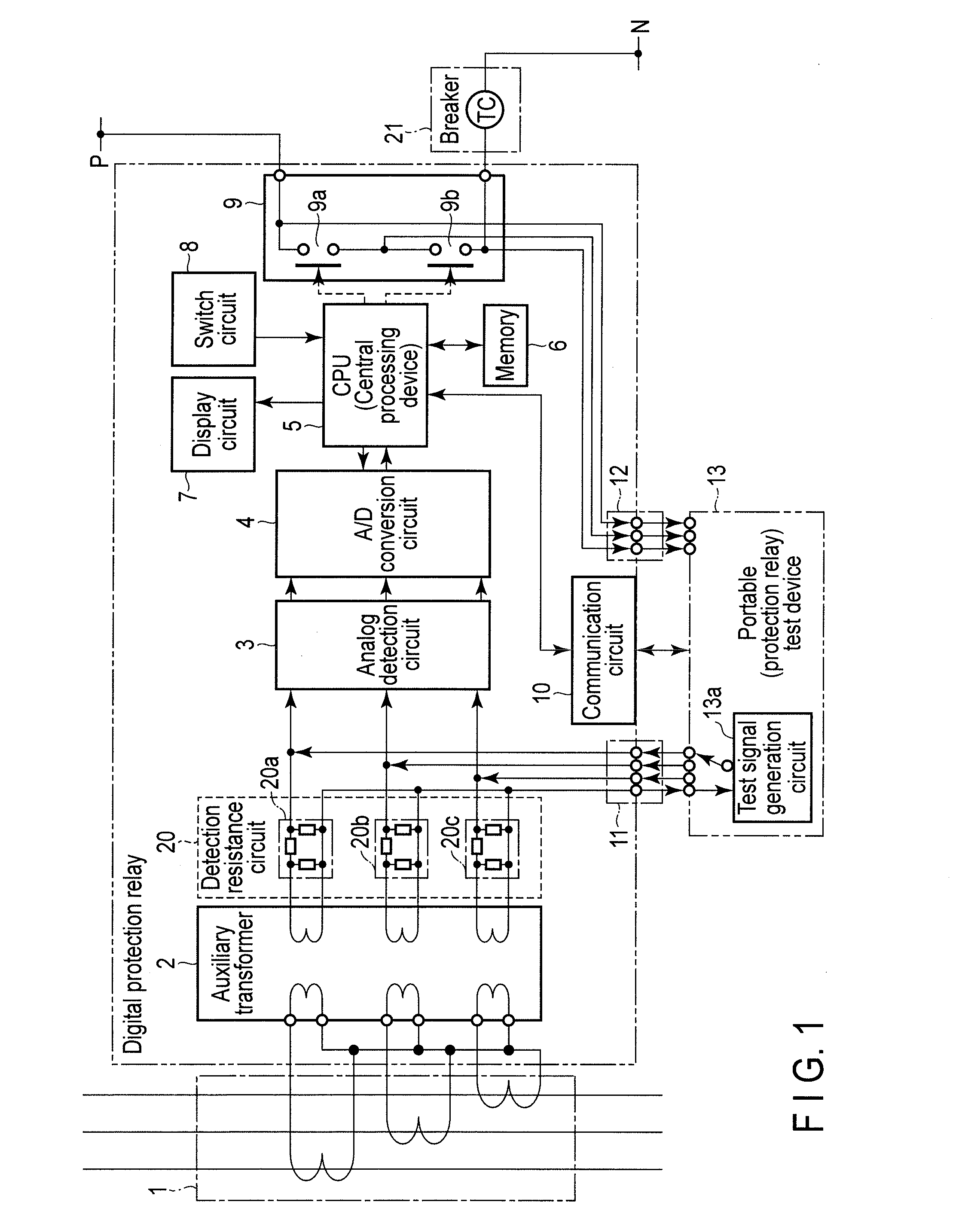
[0017]FIG. 1 is a block diagram showing an exemplary configuration of a digital protection relay according the present embodiment.

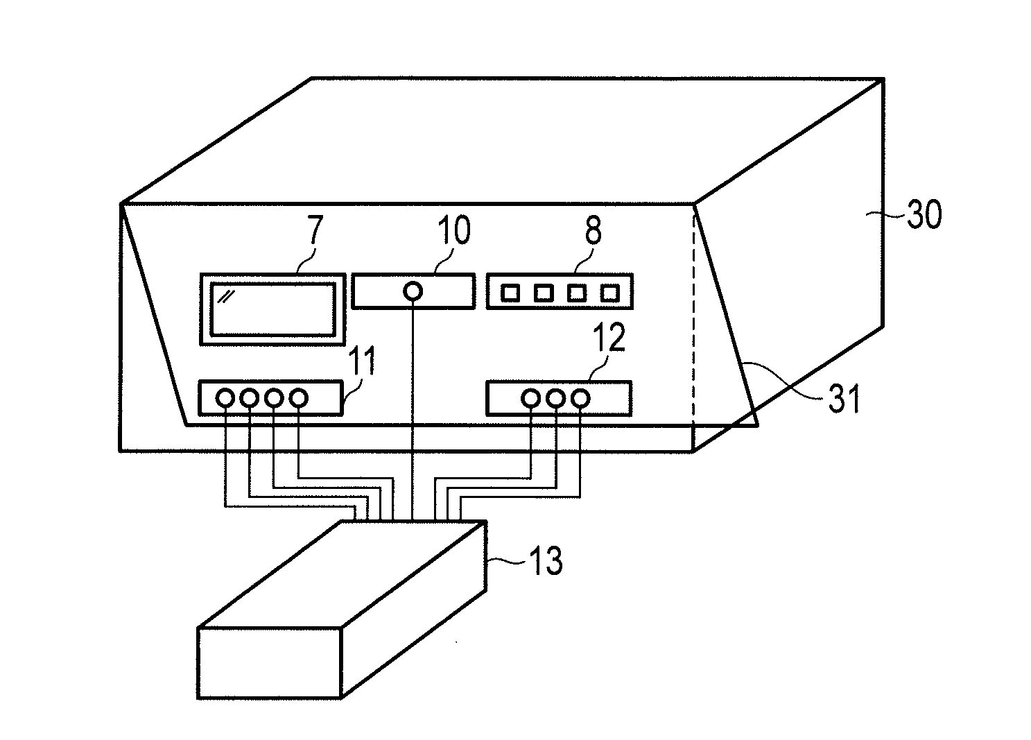
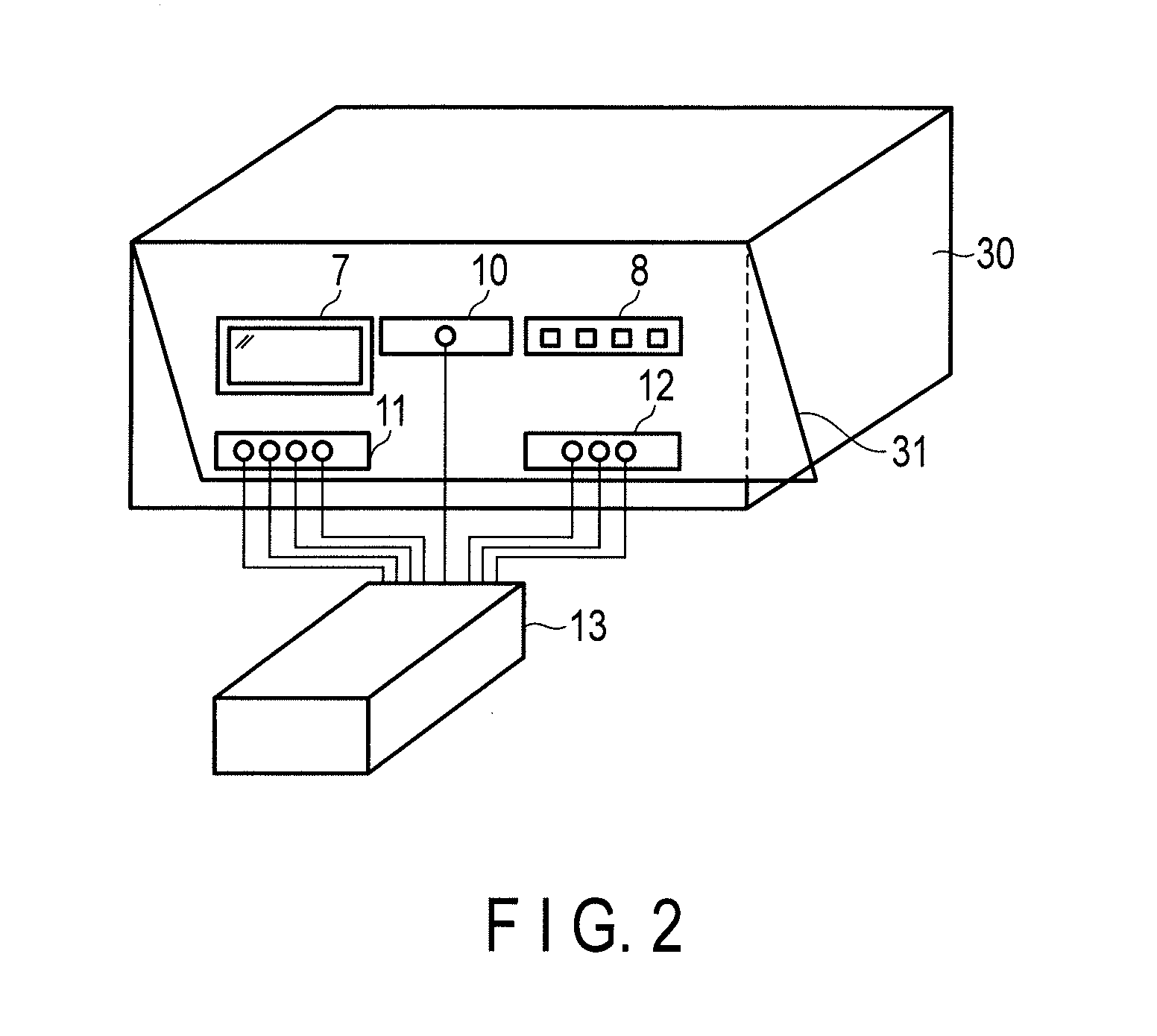
[0018]As shown in FIG. 1, the digital protection relay of the present embodiment comprises a main circuit transformer 1, an auxiliary transformer 2, an analog detection circuit 3, an A / D conversion circuit 4, a central processing unit (CPU) 5, a memory 6, a display circuit 7, a switch circuit 8, a breaker trip output contact 9, a communication circuit 10, and a test contact.

[0019]The main circuit transformer 1 is connected to the main circuit. The auxiliary transformer 2 decreases a voltage of an electrical signal from the main circuit transformer 1 to a predetermined electronic circuit level.

[0020]Between ...


PUM


Abstract

According to one embodiment, a digital protection relay includes an auxiliary transformer (2) which decreases a voltage of an electrical signal from a main circuit transformer (1) to a predetermined voltage; a detection resistance circuit (20) including a Π-type or T-type circuit including an input connected to an output of the auxiliary transformer (2); an analog detection circuit (3) which is connected to an output of the detection resistance circuit (20) and detects a quantity of electricity of an electrical signal from the auxiliary transformer (2); an A/D conversion circuit (4) connected to the analog detection circuit (3); a central processing device 5 which is connected to the A/D conversion circuit (5) and performs a protection operation; and a trip output contact (9) which is closed by processing of the central processing device (5) and operates an external breaker (21). In the digital protection relay, an input contact terminal 11 for inputting a test signal with a constant voltage from an external test device (13) to the analog detection circuit (3) as a signal corresponding to an output of the auxiliary transformer (2) is provided between the detection resistance circuit (20) and the analog detection circuit (3).

Description


Claims


Application Information

Patent Timeline
Owner KK TOSHIBA
Why Eureka
Try Eureka