
Slide assembly

Active Publication Date: 2015-07-23
KING SLIDE WORKS CO LTD +1
View PDF33 Cites 4 Cited by
  • Summary
  • Abstract
  • Description
  • Claims
  • Application Information

AI Technical Summary

Benefits of technology

The patent is about a device that allows two parts to move smoothly relative to each other. It uses ball bearings and a special holder to keep them in place, which makes it easier to move one part on top of the other.

Problems solved by technology

Nevertheless, the slide assemblies using the rollers have restriction of the loads.
Furthermore, as to compensate the assembly tolerance, the slide assemblies are not easily to be combined with soft-closing or push-open design to increase their values.
However, the high precision of the ball bearings makes them to be squeezed by the drawer and the cabinet when the assembly tolerance between the drawer and the cabinet is beyond the permissible range of the slide assembly.
This will result awkward operation of the drawers.
However, once the floating member 54 has a quality flaw such as the floating member is broken or the assembly tolerance between the drawer and the cabinet is too large, the floating member 54 might drop from the fixed member 56, and thus, the position to which the whole set of the rail assembly is installed does not permit to have the relative large tolerance between the drawer and the cabinet.

Method used


Image

  • Slide assembly
  • Slide assembly
  • Slide assembly

Examples


first embodiment

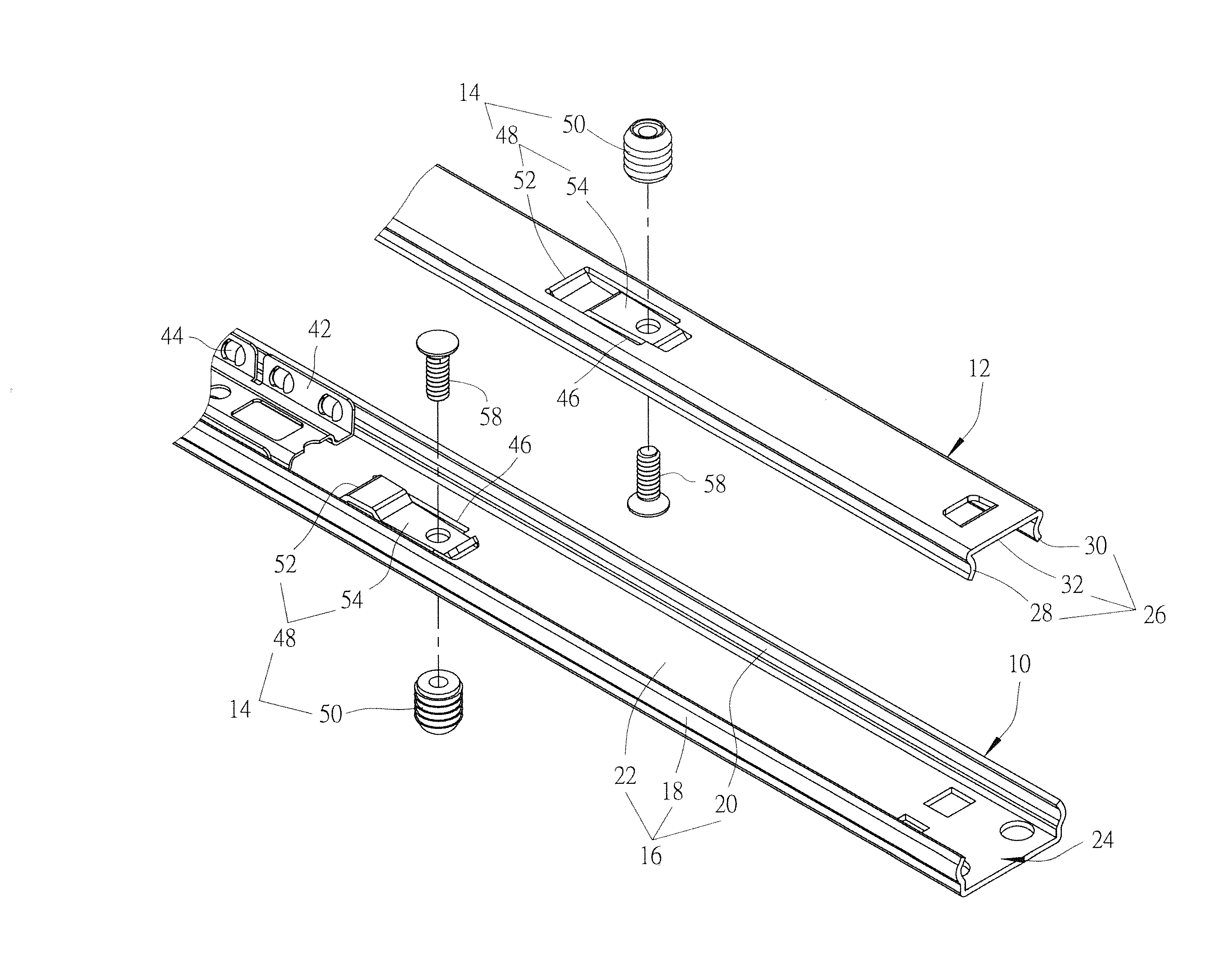
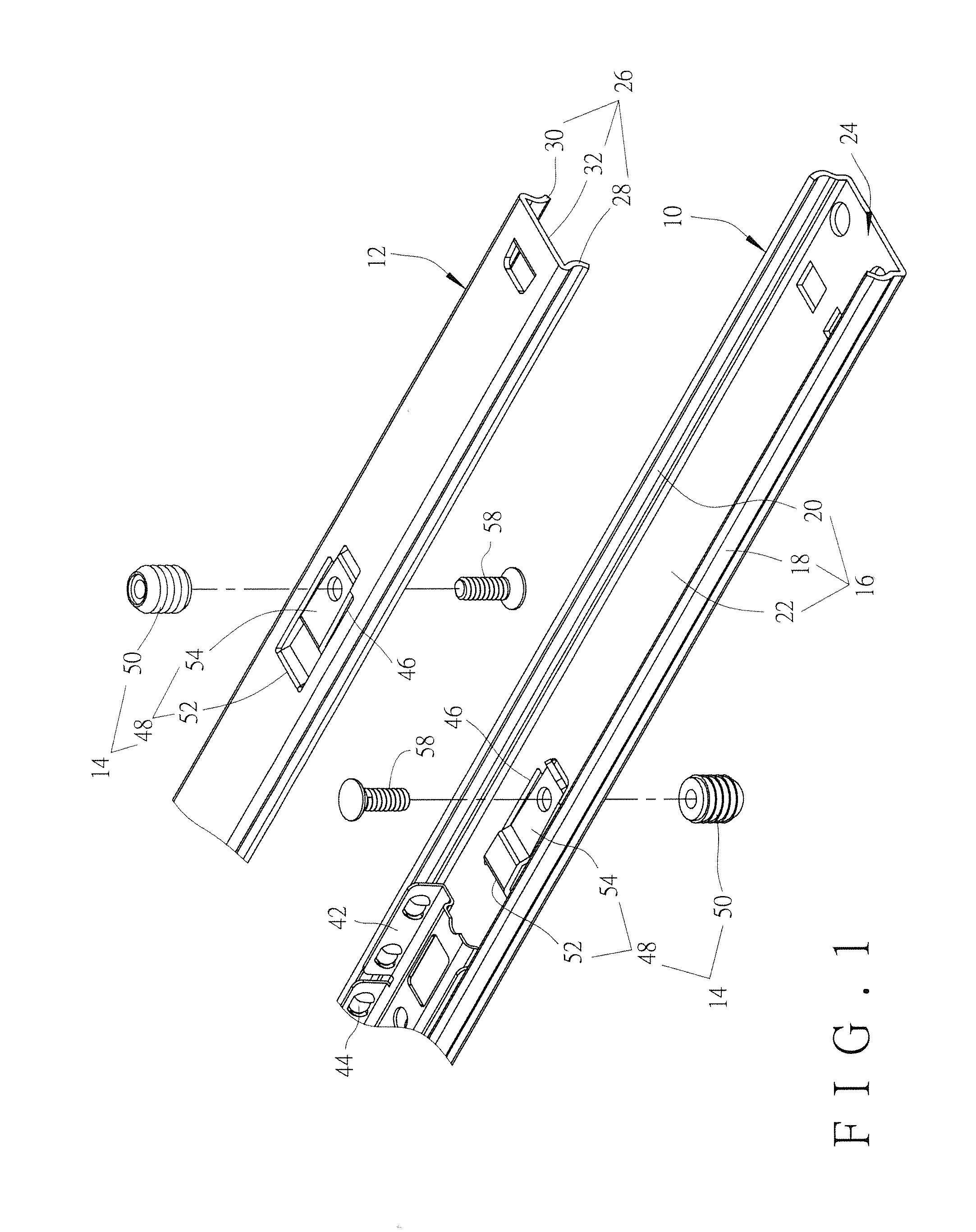
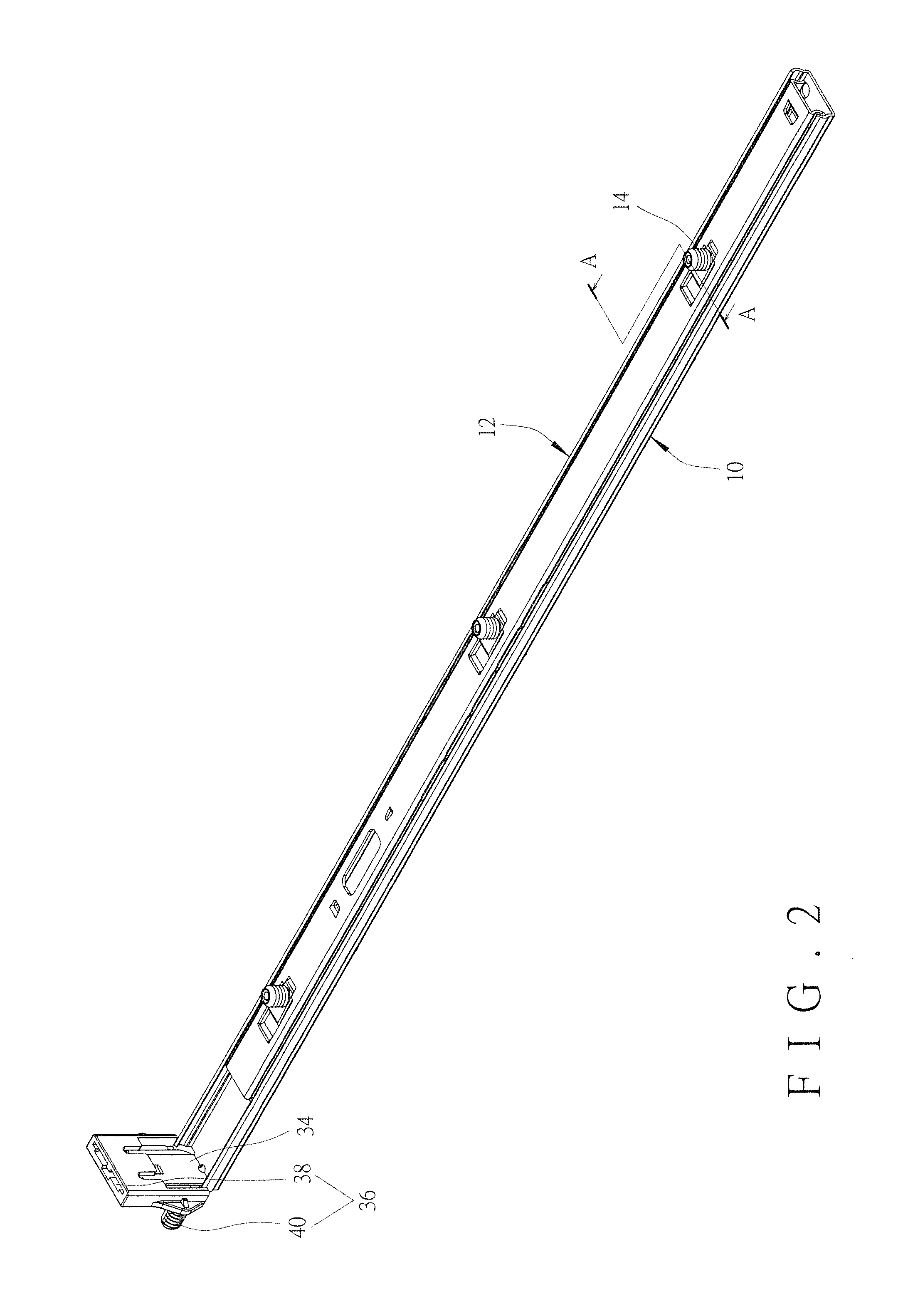
[0036]In the present invention, as shown in FIG. 6, the first elongate body 16 of the first rail 10 and the second elongate body 26 of the second rail 12 each have the opening 46 and the positioning device 14 disposed thereon, and wherein the dowel 50 of the positioning device 14 disposed on the first elongate body 16 is installed to a cabinet 62, and the dowel 50 of the positioning device 14 disposed on the second elongate body 26 is installed to a drawer 60. Since the dowels 50 are disposed on their respective resilient arms 54, when there is an assembly tolerance between the drawer 60 and the cabinet 62, the dowels 50 are capable of being moved transversely together with their respective resilient arms 54 to compensate the tolerance “d” and therefore facilitate rolling movement of the ball bearings 44 retained by the ball bearing retainer 42. Preferably, the dowel 50 and the fixing member 58 are secured together to form an integral member, which has better structural strength, so...

second embodiment

[0037]FIG. 7 shows the present invention, wherein the support member 48a and the second elongate body 26a of the second rail 12a are two individual members and are connected to each other by fixing the fixing portion 52a of the support member 48a to the second elongate body 26a of the second rail 12a by way of riveting.

third embodiment

[0038]FIGS. 8a and 8b show the present invention wherein the whole resilient arm 54a is fitted within the opening 46a of the second rail 12b and corresponds in shape to the inner wall of the opening 46a. Therefore, when the resilient arm 54a is resiliently moved within the opening 46a, the contact between the inner wall of the opening 46a and the resilient arm 54a is of large area, and thus the resilient arm 54a is better supported by the inner wall of the opening 46a.


PUM


Abstract

A slide assembly includes a first rail, a second rail and at least one positioning device. The first rail has a first elongate body. The second rail is slidable relative to the first rail and has a second elongate body. At least one of the first elongate body and the second elongate body has an opening. The at least one positioning device has a support member and a dowel. The support member has a fixing portion and a resilient arm connected to the fixing portion. The fixing portion is fixed to the at least one of the first elongate body and the second elongate body. The dowel is disposed on the resilient arm and corresponds in position to the opening.

Description

FIELD OF THE INVENTION[0001]The present invention relates to a slide assembly, and more particularly, to a slide assembly capable of quickly installed between a cabinet and a drawer.BACKGROUND OF THE INVENTION[0002]U.S. Pat. No. 5,457,867 to Maberry et al. discloses a slide assembly and is incorporated herein by reference, which uses rollers 24, 40 as sliding media and comprises a cabinet member 14 and a drawer member 38 slidably connected to the cabinet member 14. When assembling, the cabinet member 14 is fixed to a cabinet panel 12 by a pair of bushings 16, 18 and a pair of screws 20A, 20B, and the drawer member 38 is fixed to a side of a drawer 36 such that the drawer 36 is slidably connected to the cabinet member 14 by the drawer member 38 and easily slides relative to the cabinet panel 12.[0003]The slide assembly using the rollers 24, 40 mentioned above allows a larger assembly tolerance between the drawer 36 and the cabinet panel 12, so that, for the furniture manufacturers, t...

Claims


Application Information

Patent Timeline
IPC IPC(8): A47B88/14F16C29/00F16C29/04A47B88/04
CPCA47B88/14F16C29/048F16C29/004A47B88/0466A47B88/423A47B88/427A47B88/43F16C2314/72A47B88/487
Inventor CHEN, KEN-CHINGHUANG, SHIH-LUNGHUANG, TING-TSAIWANG, CHUN-CHIANG
Owner KING SLIDE WORKS CO LTD
Learn More