Tin tag dispensing and nailing tool

a technology for nailing tools and tin tags, which is applied in the direction of manufacturing tools, clothe making applications, transportation and packaging, etc., can solve the problem of reducing the life of tools

Inactive Publication Date: 2009-03-10
3J DESIGN
View PDF15 Cites 3 Cited by
  • Summary
  • Abstract
  • Description
  • Claims
  • Application Information

AI Technical Summary

Benefits of technology

[0007]Accordingly, a primary object of the present invention is to provide a tin tag supply device having improved guide means for guiding the gun-attached operating member during the displacement thereof relative to the tin tag housing as the nailing gun is displaced toward and away from the work during repeated nailing operation.
[0008]A more specific object of the invention is to provide guide means including a pair of parallel vertical guide rods that extend through corresponding through bores contained in an operating member that is formed from a hard synthetic plastic material. One end of the operating member is provided with a first projection that is adapted for connection with the nailing gun. The other end of the operating member is provided with a pair of horizontally spaced second projections that are provided with cam pins that extend laterally outwardly from the second projections into cam slots contained in the levers that operate the reciprocatory shuttle means to displace a tin tag from the bottom of a stack and to transport the removed tin tag toward the nailing station. The upper ends of the levers are pivotally connected with the upper cap portion of the body portion of the attachment tool, and the lower ends of the guide rods are fastened to the horizontal base portion of the tool body. Preferably, oil-impregnated tubular bearings of bronze or brass are mounted within the through bores of the operating member concentrically about the guide rods, thereby to lubricate the rods to improve the sliding movement of the operating member.
[0010]Preferably, the operating member is formed from a hard synthetic plastic material, such as 6619 nylon, a 66% nylon / 33% glass composition. The improved guide means eliminates side-to-side sway, produces little wear factor of the synthetic plastic material, and results in two dissimilar materials riding as a bearing surface. The original prior art guide means generated significant friction, with subsequent premature wear of the molded plastic components, thereby reducing the life of the tool. Because of the excess friction, the application of additional lubricating oil was required at regular intervals to hold the excessive wear of the molded plastic components to an absolute minimum.
[0011]The new improved vertical motion of the metal cam is designed and created through a redesigned plastic sliding mount with inserted bronze bushings, which are permanently oil-saturated for lubrication at manufacture. The two independent parallel bushings slide on polished chrome shafts attached and fixed to the base and cap housing components, thereby resulting in significantly reduced contact friction and wear through permanent lubrication from the oil-saturated bearings.
[0012]The stainless steel piston of the prior art is replaced by a shuttle plate member that is formed from resilient tempered steel that retains the memory characteristics necessary and provides jam-free operation. The spring steel shuttle plate allows for flexing under the tin tags when shuttling to the loading position, and when the tin tag is shuttled to the firing position, the punched out tongue springs upward to position a tin tag and provides vertical movement. The prior art piston design carried the entire stainless hardware plate along with the tin tag itself to the firing position for every shot. The new design pushes the tin tag to the firing position which results in moving much less hardware, produces reduction in weight, and allows for a much more efficient operation.
[0013]The body portion of the tool housing includes a top cap section that is arranged above a horizontal support plate that includes a marginal portion containing openings that receive the upper ends of the stainless steel guide rods. The operating member is spring biased upwardly into engagement with the horizontal support plate when the operating member is in its initial retracted position. Owing to the improved shuttle plate design, the recess of the plates avoid the roofing tar buildup on the tool that is always a problem during extend use in hot weather. With the plastic now riding and contacting the roofing paper instead of the metal plates, the problem of buildup is significantly reduced if not eliminated. in damp or extremely hot weather conditions, the roofing paper becomes very sticky and can create a severe problem with build-up. The roofing paper tar does not adhere to the redesigned synthetic plastic base.

Problems solved by technology

The original prior art guide means generated significant friction, with subsequent premature wear of the molded plastic components, thereby reducing the life of the tool.

Method used


Image

  • Tin tag dispensing and nailing tool
  • Tin tag dispensing and nailing tool
  • Tin tag dispensing and nailing tool

Examples


Embodiment Construction

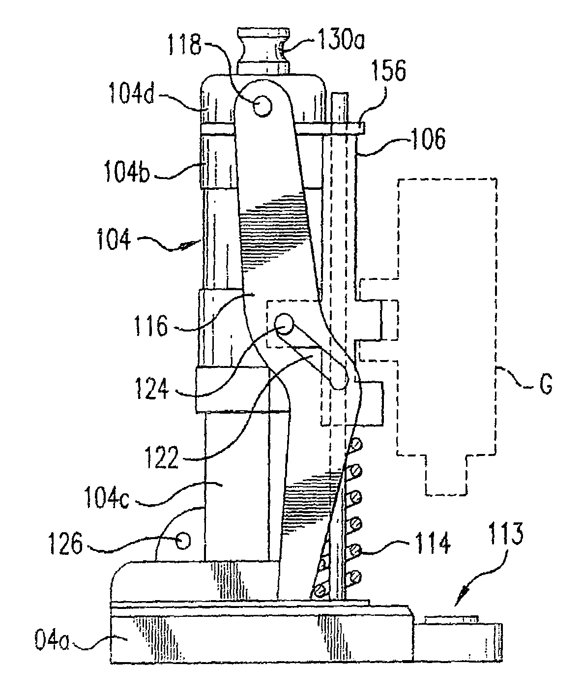
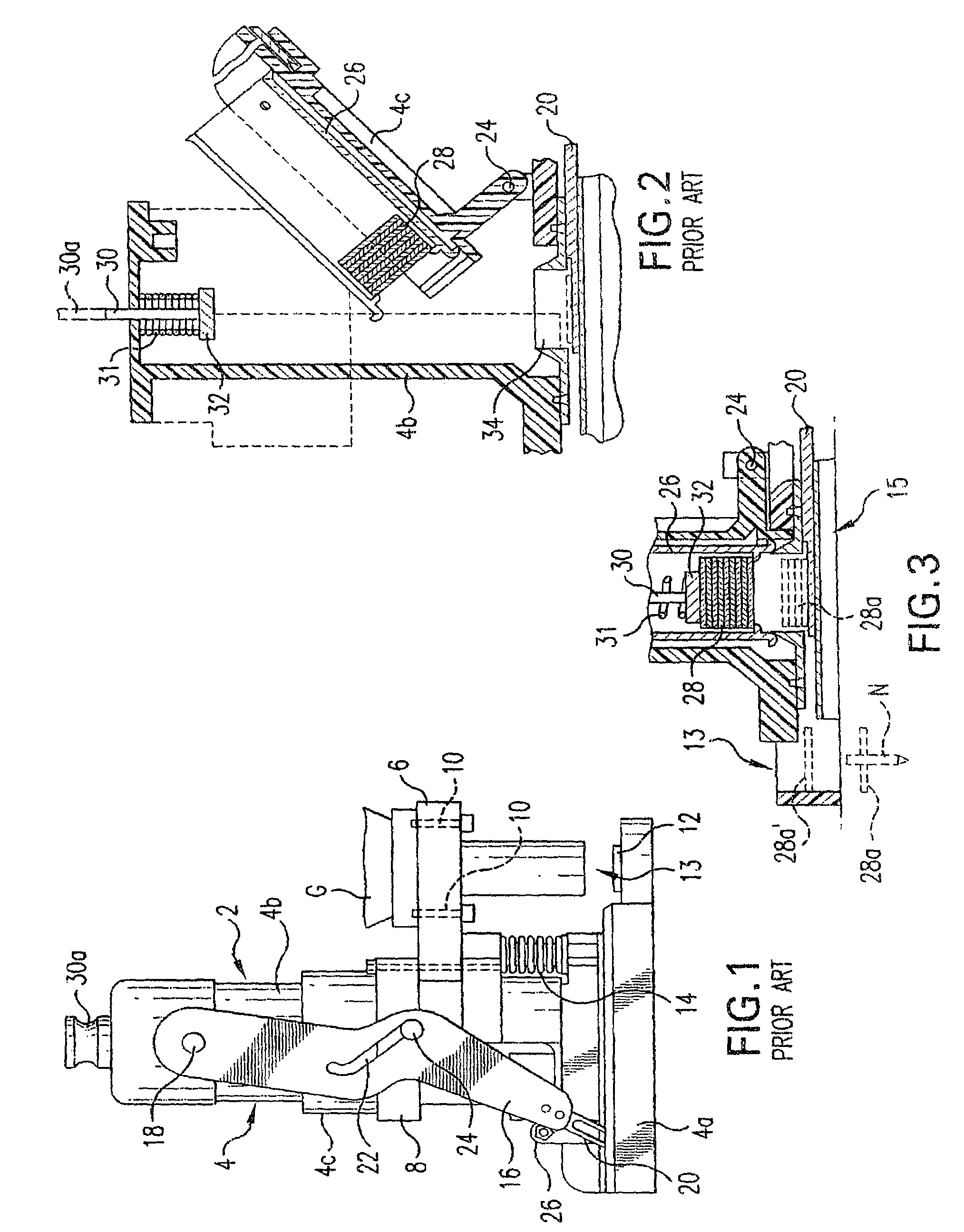
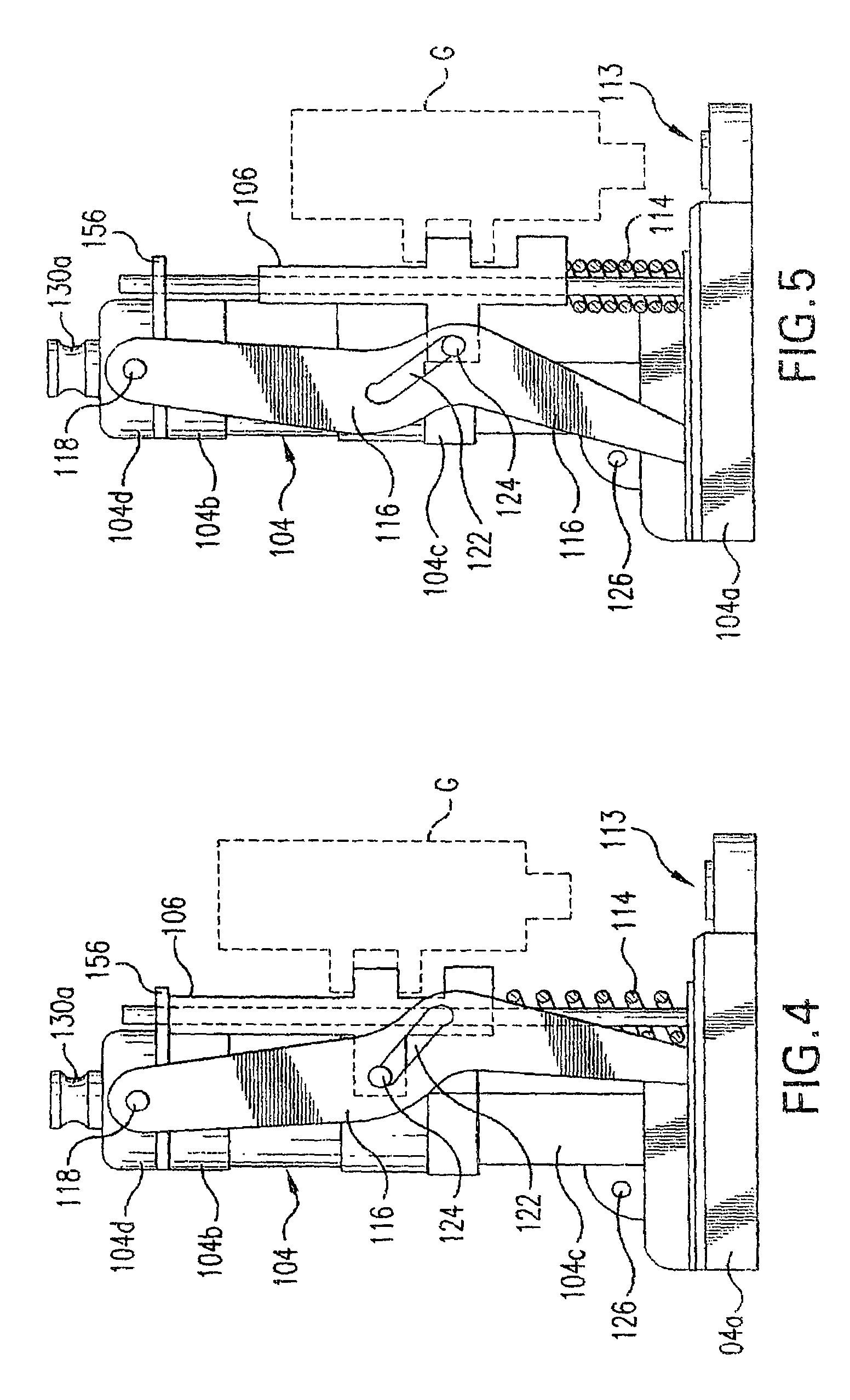
[0028]Referring first more particularly to FIGS. 1-3, it is known in the prior art to provide an attachment means 2 for supplying tin tags to a nailing gun G. The attachment means includes a housing 4 having a horizontal base portion 4a, and a generally cylindrical hollow upwardly extending vertical body portion 4b. An operating member 6 is connected by a circular sleeve 8 for vertical sliding movement relative to the body portion 4b. A conventional nailing gun G is fastened to the operating member 6 by screw thread fastener means (not shown) extending through fastening holes 10. The nailing gun G is directed downwardly toward tin tag support means 12 arranged at a nailing station 13 on the housing base portion 4a. Compression spring means 14 bias the operating member 6 upwardly toward a retracted position relative to the housing base portion 4a. Linkage means are provided for operating shuttle means to displace tin tags from a stack contained within the housing body portion 4b from...


PUM


Abstract

An improved tin tag dispensing and nailing tool includes an operating member that is adapted for connection with a roofer's nailing gun, which operating member is guided by a pair of spaced vertical guide rods for vertical sliding displacement relative to the tool housing between an upper retracted position and a lower nailing position. The operating member is formed from a synthetic plastic material and contains vertical though bores that respectively receive the guide rods. Tubular oil-impregnated bushings are mounted in the through bores concentrically about the guide rods. A linkage arrangement connects the operating member with a shuttle plate that is displaced between a loading position adjacent the tin tag supply station and a discharging position adjacent the tin tag nailing station. An integral punched-out tongue portion extends upwardly at an acute angle from the shuttle plate for engagement with the lowermost tin tag of a stack.

Description

BACKGROUND OF THE INVENTION[0001]1. Field of the Invention[0002]An improved tin tag dispensing and nailing tool includes an operating member that is adapted for connection with a roofer's nailing gun, which operating member is guided by a pair of spaced vertical guide rods for vertical sliding displacement relative to the tool housing between an upper retracted position and a lower nailing position. The operating member is formed from a synthetic plastic material and contains vertical though bores that respectively receive the guide rods. Tubular oil-impregnated metal bushings are mounted in the through bores concentrically about the guide rods. A linkage arrangement connects the operating member with a shuttle plate that is displaced between a loading position adjacent the tin tag supply station and a discharging position adjacent the tin tag nailing station. An integral punched-out tongue portion extends upwardly at an acute angle from the shuttle plate for engagement with the low...

Claims


Application Information

Patent Timeline
Patent Type & Authority Patents(United States)
IPC IPC(8): B25C7/00
CPCB25C1/006B25C5/1693
Inventor MCGUINNESS, THOMAS J.MCGUINNESS, JAMES M.MCCART, THOMAS L.
Owner 3J DESIGN
Why Eureka
Try Eureka