Support for washer or dryer

a technology for supporting frames and washing machines, which is applied in the direction of machine supports, furniture parts, other domestic objects, etc., can solve the problems of affecting the movement of the frame, the relative weight of the appliance, and the inability of a person of average strength to lift the appliance off the floor, etc., to achieve the effect of facilitating the sliding movement of the fram

Inactive Publication Date: 2003-10-30
COLEMAN CLARENCE MICHAEL
View PDF4 Cites 2 Cited by
  • Summary
  • Abstract
  • Description
  • Claims
  • Application Information

AI Technical Summary

Benefits of technology

[0011] According to yet another preferred embodiment of the invention, a wheel is attached to the frame and in contact with the base surface for facilitating sliding movement of the frame.
[0014] According to yet another preferred embodiment of the invention, a wheel is connected to the front frame member. The wheel is in contact with the base surface and facilitates sliding movement of the frame.
[0035] As shown in FIG. 1, the frame 11 is comprised of four interconnected elongate frame members: front frame member 21, rear frame member 22, right side frame member 23, and left side frame member 24. Each of the frame members 21, 22, 23, 24 is angled to form a vertical segment extending upward and a horizontal segment perpendicular to the vertical portion and extending parallel to the floor "F" (shown in FIGS. 3 and 4). Slide tracks 19, 19' are attached to side frame members 23, 24, respectively, by fasteners 16, as shown in FIGS. 2 and 9. The front frame member 21 is positioned on top of the horizontal segments of the side frame members 23, 24 at the front end of the side frame members 23, 24. Fasteners 16 extend through aligned apertures in the front frame member 21 and side frame members 23, 24. A wheel 25 is affixed at the center of the front frame member 21. The wheel 25 contacts the floor "F" and facilitates sliding movement of the frame 11.
[0038] As shown in FIG. 3, a large household appliance, such as a washing machine "M", is positioned on the frame 11 such that the front of the washing machine "M" faces the front frame member 21. The washing machine "M" rests on the horizontal segments of the frame members 21, 22, 23, 24. The vertical segments of the frame members 21, 22, 23, 24 support and stabilize the washing machine "M". The washing machine "M" and support 10 are typically mounted proximate to a wall "W" to avoid obstruction of movement through the middle of a room. In order to access the portion of the floor "F" proximate to the wall "W" that is covered by the washing machine "M", slide tracks 18, 19, 18', 19' are moved away from the brackets 13, 14, as shown in FIGS. 3, 4, 8 and 9, thereby moving frame 11 away from the wall "W". The washing machine "M" moves in unison with the frame 11 and is easily moved away from the wall "W", thereby allowing access to the portion of the floor "F" that is usually covered by the washing machine "M."

Problems solved by technology

Over time dust and other debris collects on the floor directly underneath the appliance, and in the crevice between the appliance and the wall.
Appliances such as washing machines and dryers are relatively heavy and are quite cumbersome to move.
It is virtually impossible for a person of average strength to lift them off the floor, and attempting to do so can lead to injury.
Sliding the appliance along the floor is difficult and can scratch the floor.

Method used


Image

  • Support for washer or dryer
  • Support for washer or dryer
  • Support for washer or dryer

Examples


Embodiment Construction

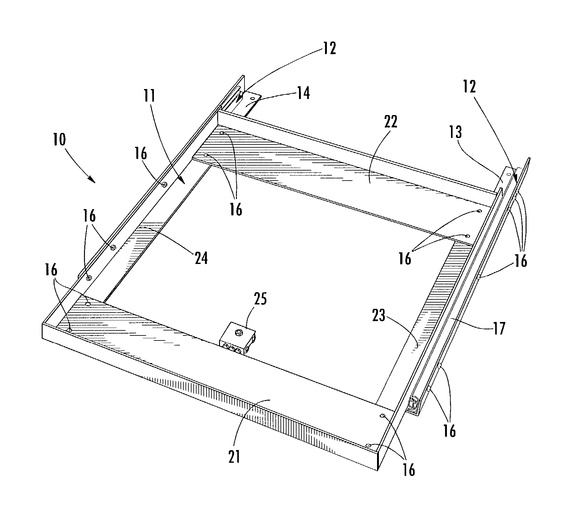
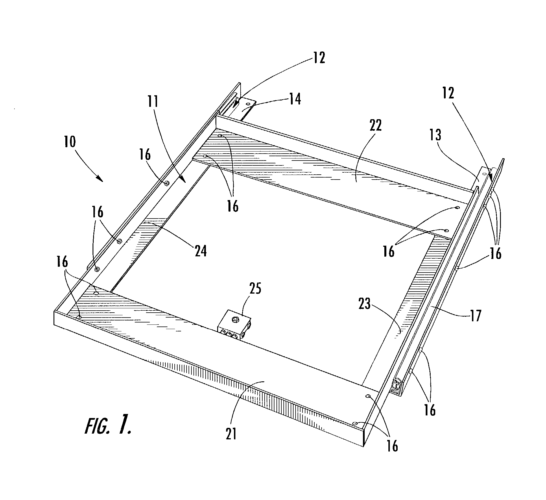
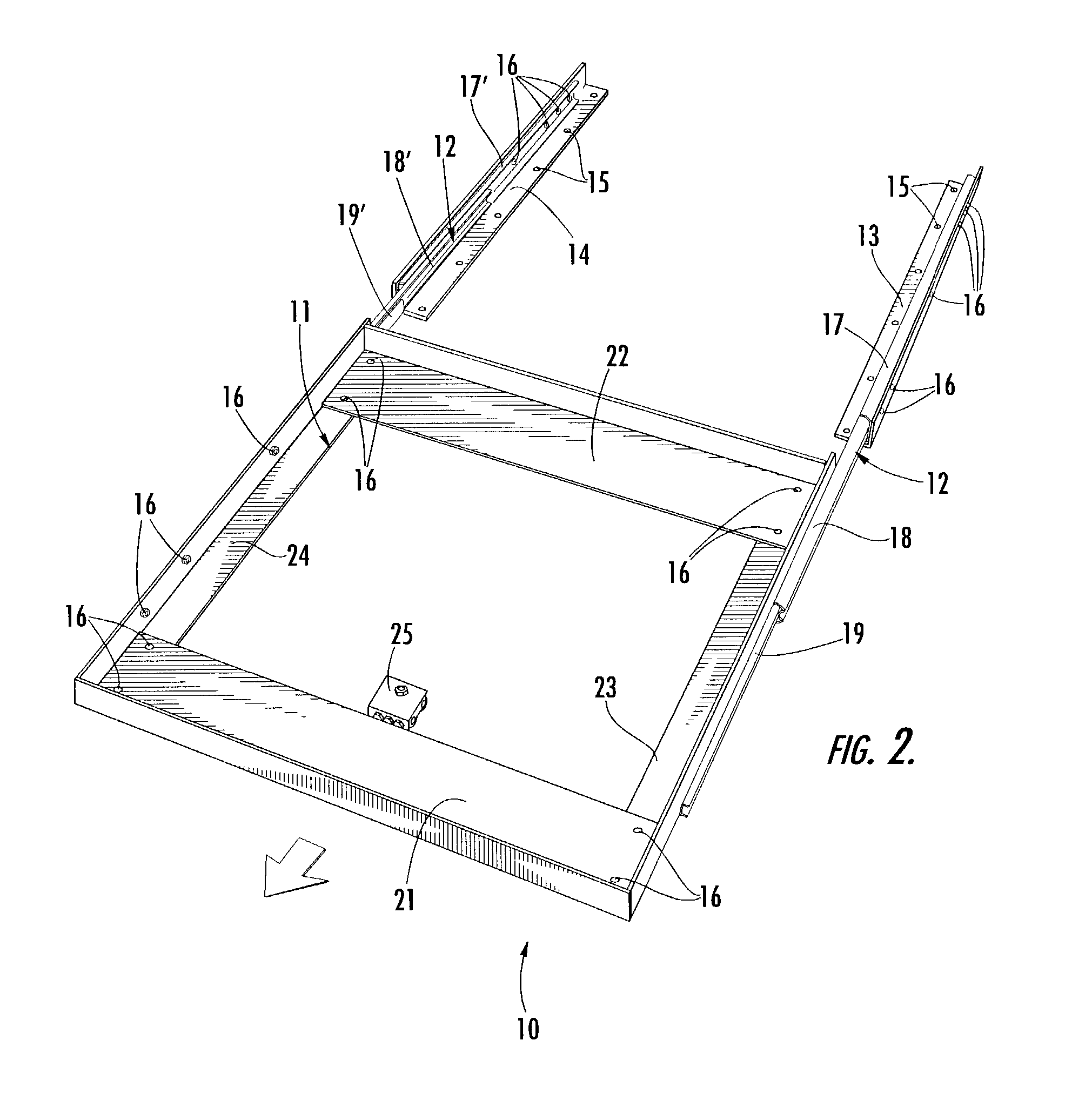
[0032] Referring now specifically to the drawings, a preferred embodiment of the appliance support according to the present invention is illustrated in FIG. 1, and shown generally at reference numeral 10. As shown in FIG. 1, the support 10 comprises a rectangular frame 11 affixed to a slide assembly 12 connected to two brackets 13, 14. The support 10 is preferably made of aluminum. A large household appliance, such as a washing machine "M", is mounted on the frame 11 as shown in FIGS. 3 and 4.

[0033] As can best be seen in FIG. 2, the brackets 13, 14 are elongate members positioned parallel to each other and mounted on a base surface, such as a floor "F" (shown in FIGS. 3 and 4). Each of the brackets 13, 14 is angled to form a vertical segment extending upward and a horizontal segment that is attached to the floor "F", by fasteners 15 extending through apertures formed in the brackets 13, 14, as shown in FIGS. 2 and 4. The vertical segments of the brackets 13, 14 are attached to the ...


PUM


Abstract

A support for moving a large appliance, particularly a washing machine or dryer, includes first and second brackets for mounting on a base surface, a slide assembly connected to the first and second brackets, and a frame for mounting the appliance. The frame is connected to the slide assembly for slidable movement relative to the first and second brackets whereby the appliance moves in unison with the frame. The slide assembly includes two sets of interconnected slide tracks cooperating with each other and a plurality of rollers to facilitate sliding movement of the frame. The perimeter of the frame is adjustable to accommodate appliances of varying depth.

Description

TECHNICAL FIELD AND BACKGROUND OF THE INVENTION[0001] The invention relates to a support frame for a large appliance, particularly a washer or dryer, that enables persons of varying strength to easily and quickly move the large appliance to access areas normally obstructed by the appliance. Large household appliances such as washers and dryers are typically positioned directly against a wall for practical reasons such as proximity to electrical outlets and conserving space, as well as for aesthetic reasons. Over time dust and other debris collects on the floor directly underneath the appliance, and in the crevice between the appliance and the wall. In addition, it is periodically necessary to access the back of the appliance for maintenance or repairs of the appliance. Also, at times it is necessary to access the electrical outlet directly behind the appliance to which the appliance is connected.[0002] Appliances such as washing machines and dryers are relatively heavy and are quite...

Claims


Application Information

Patent Timeline
Patent Type & Authority Applications(United States)
IPC IPC(8): B65D19/00
CPCB65D19/0002
Inventor COLEMAN, CLARENCE MICHAEL
Owner COLEMAN CLARENCE MICHAEL
Why Eureka
Try Eureka