Boat hoist

a hoist and boat technology, applied in special-purpose vessels, floating buildings, transportation and packaging, etc., can solve the problems of difficult assembly and maintenance, affecting the reliability of the hoist, etc., and achieve the effect of facilitating the sliding movement of the platform

Inactive Publication Date: 2006-09-07
MULTI AUTOMATED PRODS
View PDF18 Cites 5 Cited by
  • Summary
  • Abstract
  • Description
  • Claims
  • Application Information

AI Technical Summary

Benefits of technology

[0010] A hoist having two vertical frames forming the two sides of the hoist, each of the two vertical frames having a lower portion and an upper portion. One or more cross tubes connects to the two vertical frames with one or more diagonal tubes mounted to the one or more cross tubes. Each diagonal tube is positioned at an angle with respect to the lower portion of the two vertical frames. A platform is slidably connected to the diagonal tubes and serves as a track for sliding the platform along the length of the diagonal tubes. One or more roller assemblies are connected between the platform and the diagonal tubes for the purpose of facilitating the sliding movement of the platform along the length of the diagonal tubes.
[0011] The boat hoist is to provide a system, which will safely store watercraft with ease of operation.
[0012] The boat hoist also provides a system with fewer parts therefore improving assembly and maintenance required. Additionally the hoist uses a roller wheel assembly that provides consistent reliability.

Problems solved by technology

Existing boat hoist assemblies often incorporate complex mechanisms with a large number of parts which make it difficult to assemble and maintain.
Additionally, the complexity of these designs will effect the reliability of the hoist.

Method used


Image

  • Boat hoist
  • Boat hoist
  • Boat hoist

Examples


Embodiment Construction

[0019] The following description of the preferred embodiment(s) is merely exemplary in nature and is in no way intended to limit the invention, its application, or uses.

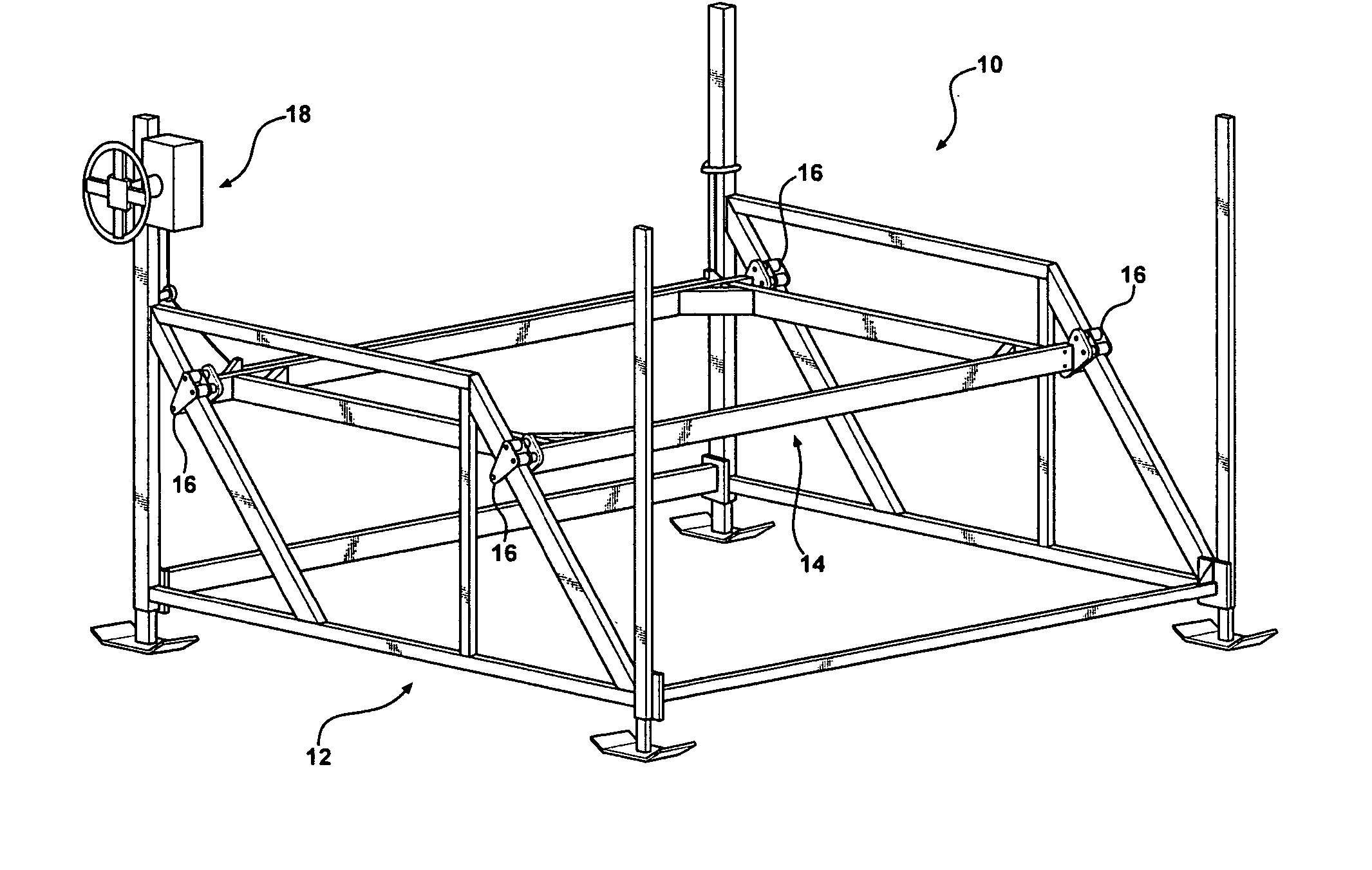
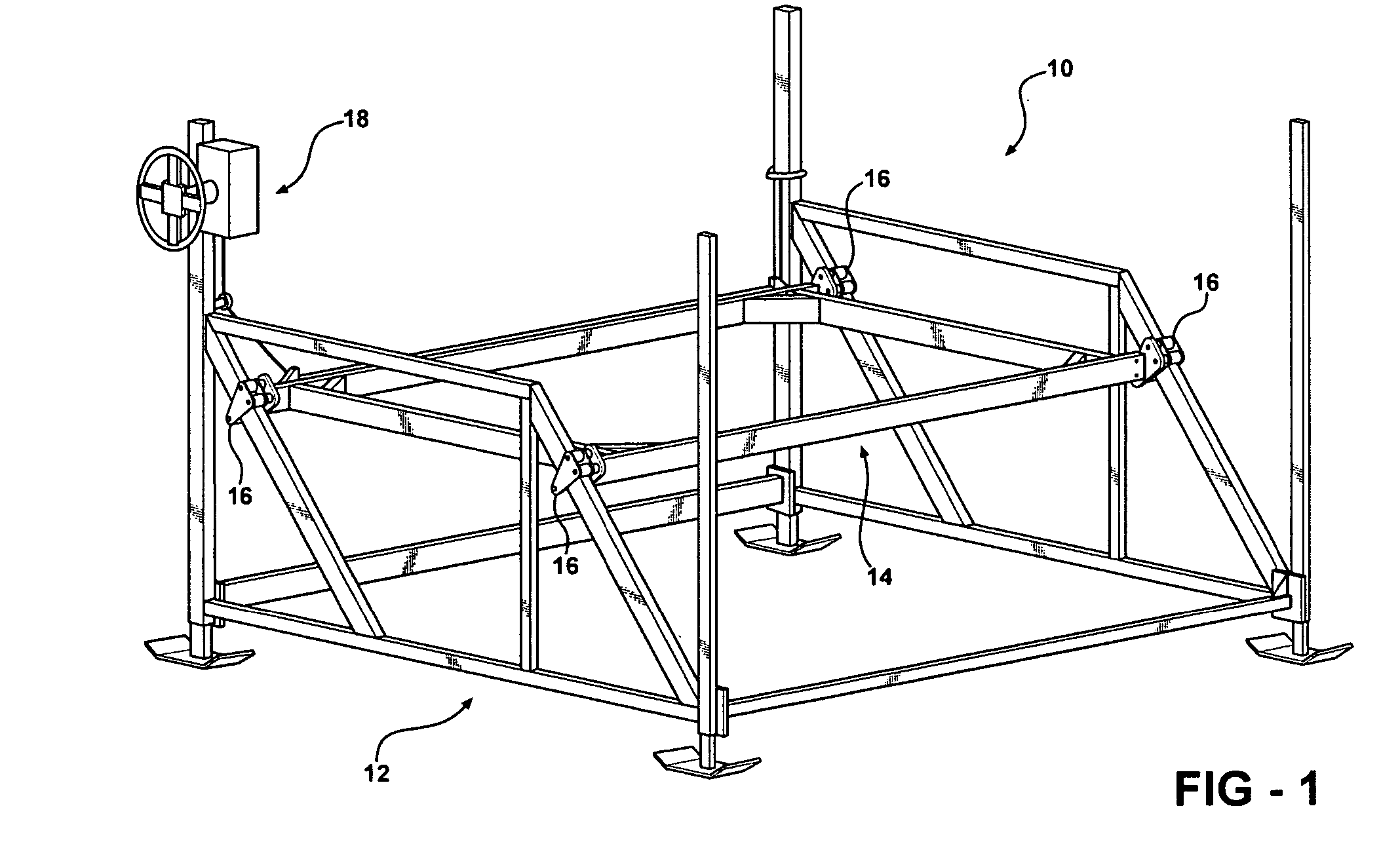
[0020] Referring now to FIGS. 1-4 a boat hoist 10 is shown as having a mainframe 12, moving platform 14, roller assembly units 16 and a drive assembly or suspension system 18.

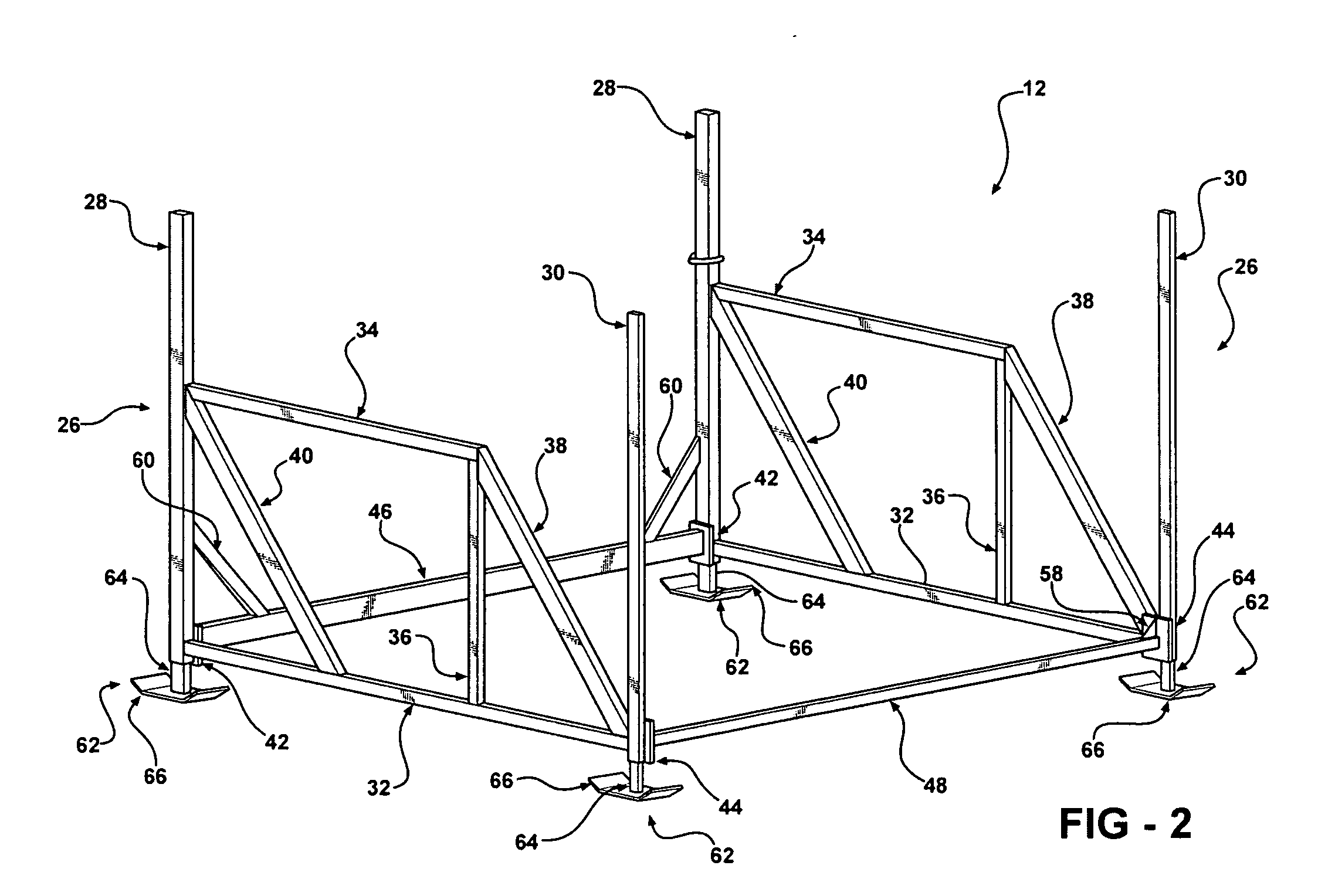
[0021]FIG. 2 illustrates a perspective view of the main frame 12 which has two vertical side frames 26 which are a welded construction of extruded aluminum tubing material. The two vertical sides 26 are identical in material and construction except that one is a right hand and one is a left hand.

[0022] Each vertical side frame 26 is constructed of a front vertical tube 28 and rear vertical tube 30 connected longitudinally across the bottom by lower tube 32. Across the top of each side frame 26 is a top tube 34 that connects to front vertical tube 28 and a center vertical tube 36, and a rear diagonal tube 38. A front diagonal tube 40 is connec...


PUM


Abstract

A boat hoist utilizing a lightweight frame for support of a moving platform, which traverses the frame lifting the watercraft above the surface of the water. Minimal force applied to a single hand wheel on a winch, and pulley system with a flexible cable, will provide the drive to lift and lower the moving platform. This invention distributes the load between the four-roller assemblies without creating undue torsional and / or twisting force to the moving platform, the load is carried by roller assembly and frame and not solely the flexible cable. The dual inclined roller surface, pulley system, and roller wheels reduce the force required to raise the platform. Legs support the lightweight frame assembly, and are adjustable to accommodate uneven terrain on the bottom surface. This system utilizes fewer flexible cables and moving parts than traditional systems, as well as all moving parts remain above the waterline during storage for improved reliability and reduced maintenance.

Description

CROSS-REFERENCE TO RELATED APPLICATIONS [0001] This application claims the benefit of U.S. Provisional Application No. 60 / 657,790, filed Mar. 2, 2005. The disclosure of which is incorporated herein by reference.FIELD OF THE INVENTION [0002] The present invention relates in general to lifting devices for the purpose of raising and storing watercraft, specifically to a boat hoist utilizing a novel load distribution system. BACKGROUND OF THE INVENTION [0003] Existing lift mechanisms incorporate various methods to elevate a watercraft. The following U.S. Patents exemplify current systems and technology in the boat hoist market: [0004] U.S. Pat. No. 4,850,741 illustrates and describes a boat hoist having a hydraulic powered, cantilevered supported lifting mechanism. [0005] U.S. Pat. No. 32,118 illustrates and describes a boat hoist having a vertical lifting system utilizing multiple cables, pulleys and winch as a drive and support system. [0006] U.S. Pat. No. 4,109,896 illustrates and de...

Claims


Application Information

Patent Timeline
Patent Type & Authority Applications(United States)
IPC IPC(8): B63C3/06B63C7/00
CPCB63C3/06
Inventor MASTERS, K. GREGG
Owner MULTI AUTOMATED PRODS
Why Eureka
Try Eureka