Candlelight simulation electronic candle

a candle and simulation technology, applied in semiconductor devices, lighting and heating apparatuses, and light sources with built-in power, etc., can solve problems such as insufficient visual experience, inability to achieve deceptive objectives, and gradual degradation of lighting functions

Inactive Publication Date: 2015-07-23
LEE JERRY
View PDF5 Cites 32 Cited by
  • Summary
  • Abstract
  • Description
  • Claims
  • Application Information

AI Technical Summary

Benefits of technology

[0023](1) In the power-on state, the swinging mechanism drives the lens to swing along with the lens holder; the elliptical shadow which looks like the flame is formed on the wall by the light emitted from the lens; and the elliptical shadow flickers, and hence the visual effect of the real flame can be simulated and the deceptive objective can be achieved.
[0024](2) As the wick of the candlelight simulation electronic candle provided by the present invention also simulates the shape of a real candle wick, the wick cannot be easily perceived to be false in the power-off state, and hence more real visual effect of the candlelight simulation electronic candle provided by the present invention can be achieved.

Problems solved by technology

However, along with the widespread use of electronic light sources, the lighting function is gradually degraded, and the requirement of people on the candle is converted from practicability to ornamental property and sentiment.
However, in the power-off state, both the swinging mechanism and the light-emitting element stops operating, and hence the flame sheet looks untrue and the state is greatly different from the real candle extinguishing state, and consequently people can understand fully at one glance that the device is a fake candle device.
Therefore, the deceptive objective cannot be achieved and the visual experience is not real enough.

Method used


Image

  • Candlelight simulation electronic candle
  • Candlelight simulation electronic candle
  • Candlelight simulation electronic candle

Examples


embodiment 1

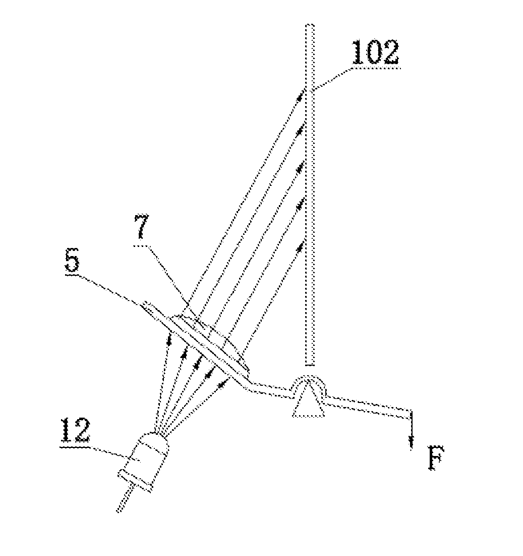
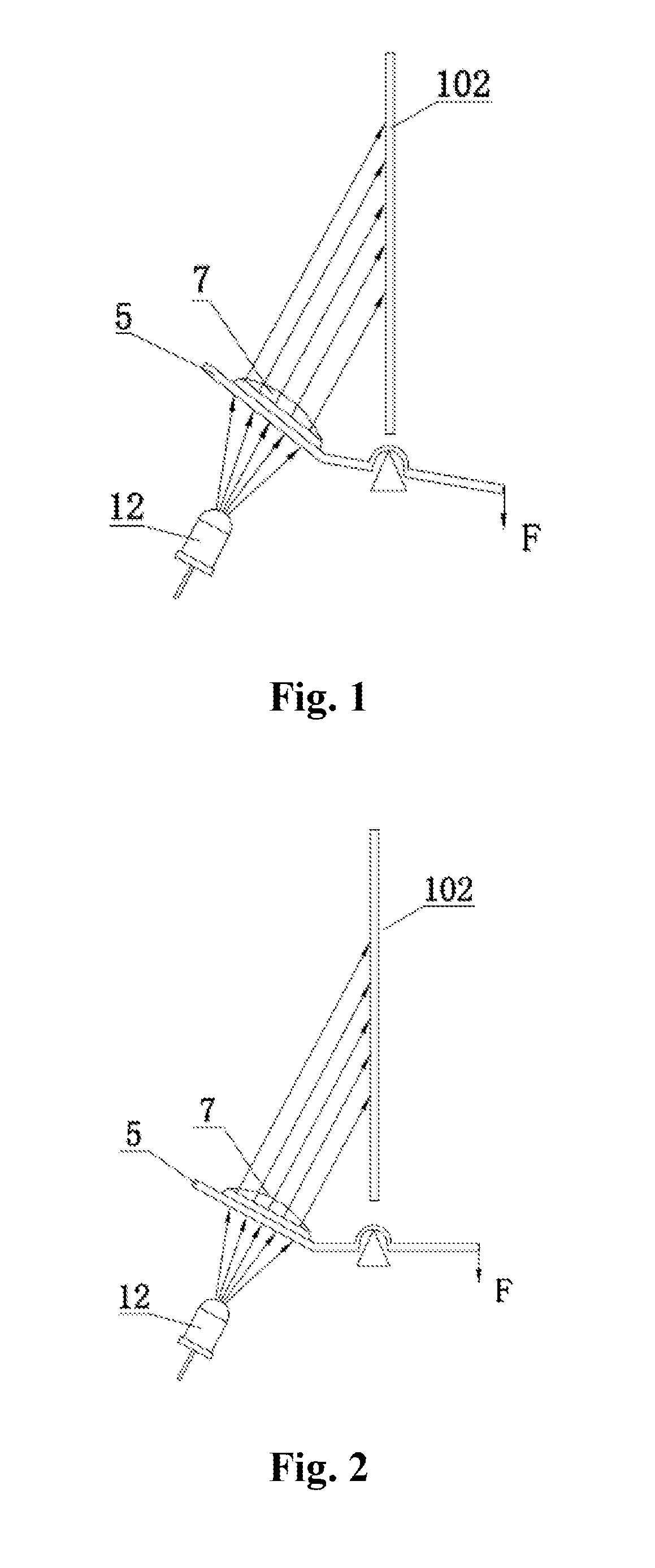
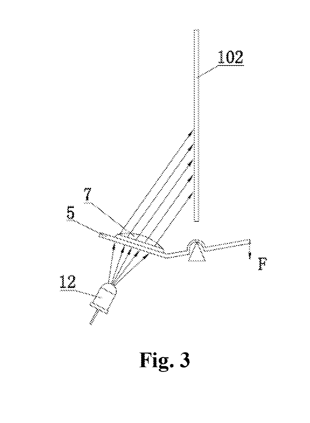
[0041]As illustrated in FIGS. 2 to 6, the present invention relates to a candlelight simulation electronic candle, which comprises a candle body shell 1 and a candle body base 2, wherein the candle body shell 1 is connected with the candle body base 2 to form an accommodating space; a wick 3, a casing through hole 101 and a wall 102 are formed on the upper end of the candle body shell 1; the wick 3 simulates the shape of a real candle wick and is disposed between the casing through hole 101 and the wall 102; the accommodating space is provided with a mounting bracket 4 and a lens holder 5 which are movably connected with each other, and is also provided with a swinging mechanism which is configured to drive the lens holder 5 to swing around the mounting bracket 4; the mounting bracket 4 and the lens holder 5 are respectively provided with a light-emitting element 12 and a lens 7; a gap is formed between the light-emitting element 12 and the lens 7; in the power-on state, light of th...

embodiment 2

[0056]The technical proposal of the embodiment is basically the same with that of the embodiment 1. The difference is as follows:

[0057]As illustrated in FIG. 10, in the embodiment, the wall 102 is disposed on the candle body shell 1. The difference of the technical proposal of the embodiment with that of the embodiment 1 is that: the shape and the position of the wall 102 are different.

embodiment 3

[0058]The technical proposal of the embodiment is basically the same with that of the embodiment 1. The differences are as follows:

[0059]As illustrated in FIG. 11, the swinging mechanism includes a fan 15 which is mounted in the accommodating space; the lens holder 5 is provided with a windward baffle 16; and in the power-on state, the baffle 16 is driven to swing by the wind force generated by the fan 15. More specifically, the lens holder 5, the lens 7 and the baffle 16 are mutually fixed; and when the baffle 16 is driven to swing by the wind force generated by the fan 15, the lens holder 5 and the lens 7 will swing along with the baffle 16, and hence the objective of the flickering of the shadow on the wall 102 can be achieved.

[0060]The main technical proposal of the embodiment is basically the same with that of the embodiment 1. Unexplained characteristics in the embodiment adopt the explanation in the embodiment and will not be further described herein.


PUM


Abstract

The present invention relates to a candlelight simulation electronic candle, which comprises a candle body shell and a candle body base, wherein the candle body shell is connected with the candle body base to form an accommodating space; a wick, a casing through hole and a wall are formed on the upper end of the candle body shell; the wick is disposed between the casing through hole and the wall; the accommodating space is provided with a mounting bracket and a lens holder which are hinged to each other, and is also provided with a swinging mechanism which is configured to drive the lens holder to swing around the mounting bracket; and the mounting bracket and the lens holder are respectively provided with a light-emitting element and a lens. to form a flame.

Description

FIELD OF THE INVENTION[0001]The present invention relates to the technical field of electronic light-emitting devices, in particular to a candlelight simulation electronic candle.BACKGROUND OF THE INVENTION[0002]In the everyday life, people originally take candle as a lighting fixture. However, along with the widespread use of electronic light sources, the lighting function is gradually degraded, and the requirement of people on the candle is converted from practicability to ornamental property and sentiment. Therefore, various electronic light-emitting devices such as electronic flash candles, music candles and simulative kerosene lamps are produced.[0003]The prior art discloses an electronic candle, which comprises a light-emitting element, a flame sheet and a swinging mechanism capable of driving the flame sheet to swing, wherein the flame sheet simulates the shape of a real flame after a candle is ignited. After the electrification, the flame sheet is driven to swing by the swin...

Claims


Application Information

Patent Timeline
Patent Type & Authority Applications(United States)
IPC IPC(8): F21V23/04F21S10/02F21V23/00F21S10/04
CPCF21V23/0457F21V23/00F21S10/02F21S10/046F21S6/001F21S9/02F21S10/007F21V23/0464F21W2121/00F21Y2115/10
Inventor LEE, JERRY
Owner LEE JERRY
Why Eureka
Try Eureka