Three-dimensional object preview device, three-dimensional printing apparatus, and three-dimensional object preview method

a three-dimensional object and preview device technology, applied in the direction of digital output to print units, instruments, manufacturing tools, etc., can solve the problems of partial loss of cross-sectional image data, defect in generated cross-sectional image data, and no method known in the art that enables an operator to determin

Active Publication Date: 2015-07-23
ROLAND DG CORP
View PDF3 Cites 18 Cited by
  • Summary
  • Abstract
  • Description
  • Claims
  • Application Information

AI Technical Summary

Benefits of technology

[0016]Various preferred embodiments of the present invention enable, before beginning to form a three-dimensional object, display of a three-dimensional model representing a shape of the three-dimensional object to be actually formed. This enables an operator to, for example, adjust layer thicknesses so that the three-dimensional object has a desired surface smoothness or correct defective cross-sectional image data while observing the three-dimensional model. Consequently, the three-dimensional object is easily formed as desired.

Problems solved by technology

If the target object has a complicated shape, an error or miscomputation, for example, can occur during the computation, resulting in a defect in the generated cross-sectional image data, e.g., a partial loss of the cross-sectional image data.
Unfortunately, there is no method known in the art that enables an operator to determine a defect in cross-sectional image data before actually starting to form a three-dimensional object.
Unfortunately, no technique known in the art allows an operator to find how smooth the surface of a three-dimensional object is until the three-dimensional object is actually formed.
Thus, in some cases, the surface of a three-dimensional object, which has actually been formed, is not as smooth as an operator has expected.
This, however, makes forming of the three-dimensional object time-consuming.

Method used


Image

  • Three-dimensional object preview device, three-dimensional printing apparatus, and three-dimensional object preview method
  • Three-dimensional object preview device, three-dimensional printing apparatus, and three-dimensional object preview method
  • Three-dimensional object preview device, three-dimensional printing apparatus, and three-dimensional object preview method

Examples


Embodiment Construction

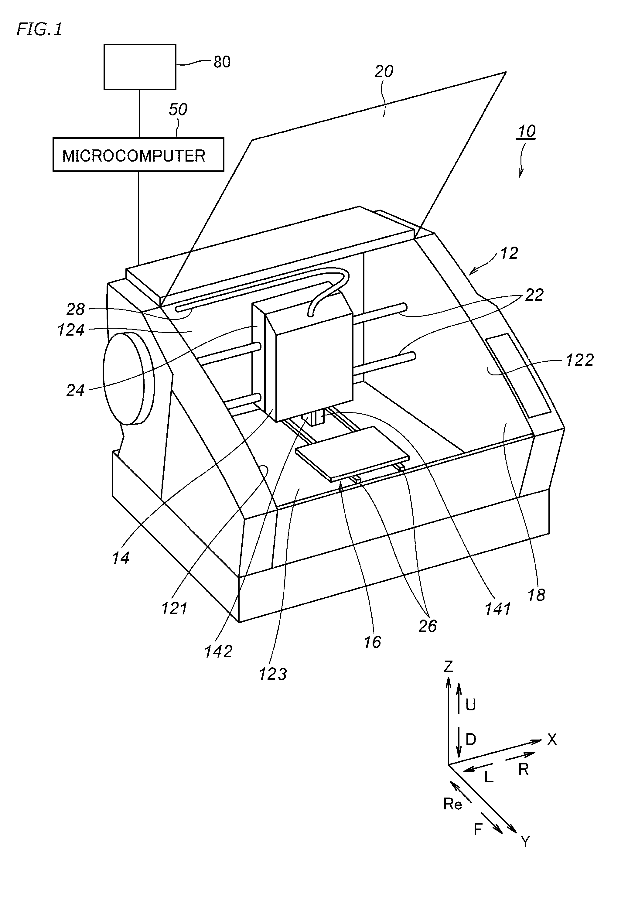
[0026]A three-dimensional object preview device, a three-dimensional printing apparatus, and a three-dimensional object preview method according to preferred embodiments of the present invention will now be described in detail with reference to the accompanying drawings. The terms “right”, “left”, “up”, and “down” in the following description respectively refer to right, left, up, and down with respect to an operator (not illustrated) in front of a three-dimensional printing apparatus 10 illustrated in FIG. 1. The term “forward” refers to a direction from the rear of the three-dimensional printing apparatus 10 toward the front of the three-dimensional printing apparatus 10. The term “rearward” refers to a direction from the front of the three-dimensional printing apparatus 10 toward the rear of the three-dimensional printing apparatus 10. The reference signs “F”, “Re”, “R”, “L”, “U”, and “D” in the drawings respectively refer to front, rear, right, left, up, and down. It is to be no...


PUM

PropertyMeasurementUnit
thicknessaaaaaaaaaa
shapeaaaaaaaaaa
weightaaaaaaaaaa

Abstract

A three-dimensional object preview device includes a cross-sectional image data generation section configured to generate cross-sectional image data representing a cross-sectional shape of each layer of a three-dimensional object, a two-dimensional coordinate data acquisition section configured to acquire first two-dimensional coordinate data from the cross-sectional image data, a two-dimensional coordinate data conversion section configured to convert, using triangulation, the first two-dimensional coordinate data into second two-dimensional coordinate data, a three-dimensional coordinate data generation section configured to add Z-axis coordinate information to the second two-dimensional coordinate data to generate three-dimensional coordinate data, a layer image data generation section configured to add layer thickness information to the three-dimensional coordinate data, thus generating layer image data, a printing image data generation section configured to generate, using the layer image data, printing image data representing a three-dimensional model, and a display section configured to cause a display device to display the three-dimensional model.

Description

[0001]This application claims priority to Patent Application No. 2014-7711 filed in Japan on Jan. 20, 2014, the entire contents of which are hereby incorporated by reference.BACKGROUND OF THE INVENTION[0002]1. Field of the Invention[0003]The present invention relates to three-dimensional object preview devices, three-dimensional printing apparatuses, and three-dimensional object preview methods.[0004]2. Description of the Related Art[0005]A three-dimensional object is formed, as is known in the art, using three-dimensional data representing a shape of the three-dimensional object. Such a technique is disclosed in JP 02-130132 A, for example.[0006]A three-dimensional printing apparatus disclosed in JP 02-130132 A includes a discharge nozzle from which liquid photo-curable resin is discharged. This discharge nozzle is movable along X, Y, and Z axes of an XYZ rectangular coordinate system. The photo-curable resin discharged from the discharge nozzle is exposed to light. The photo-curab...

Claims


Application Information

Patent Timeline
Patent Type & Authority Applications(United States)
IPC IPC(8): G06F3/12B29C67/00
CPCG06F3/1256B29C67/0055G06F3/1208B33Y10/00B33Y30/00B33Y50/00B29C64/112B29C64/393B29C64/40H04N1/6011
Inventor KOBAYASHI, KOUICHI
Owner ROLAND DG CORP
Why Eureka
Try Eureka