
Imaging device, image processing method, and recording medium

Inactive Publication Date: 2008-04-15
RICOH KK
View PDF17 Cites 9 Cited by
  • Summary
  • Abstract
  • Description
  • Claims
  • Application Information

AI Technical Summary

Benefits of technology

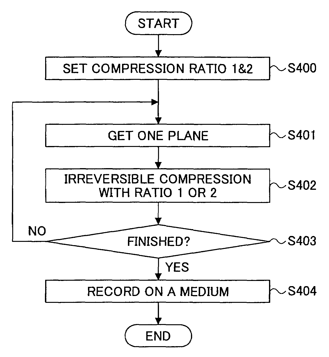
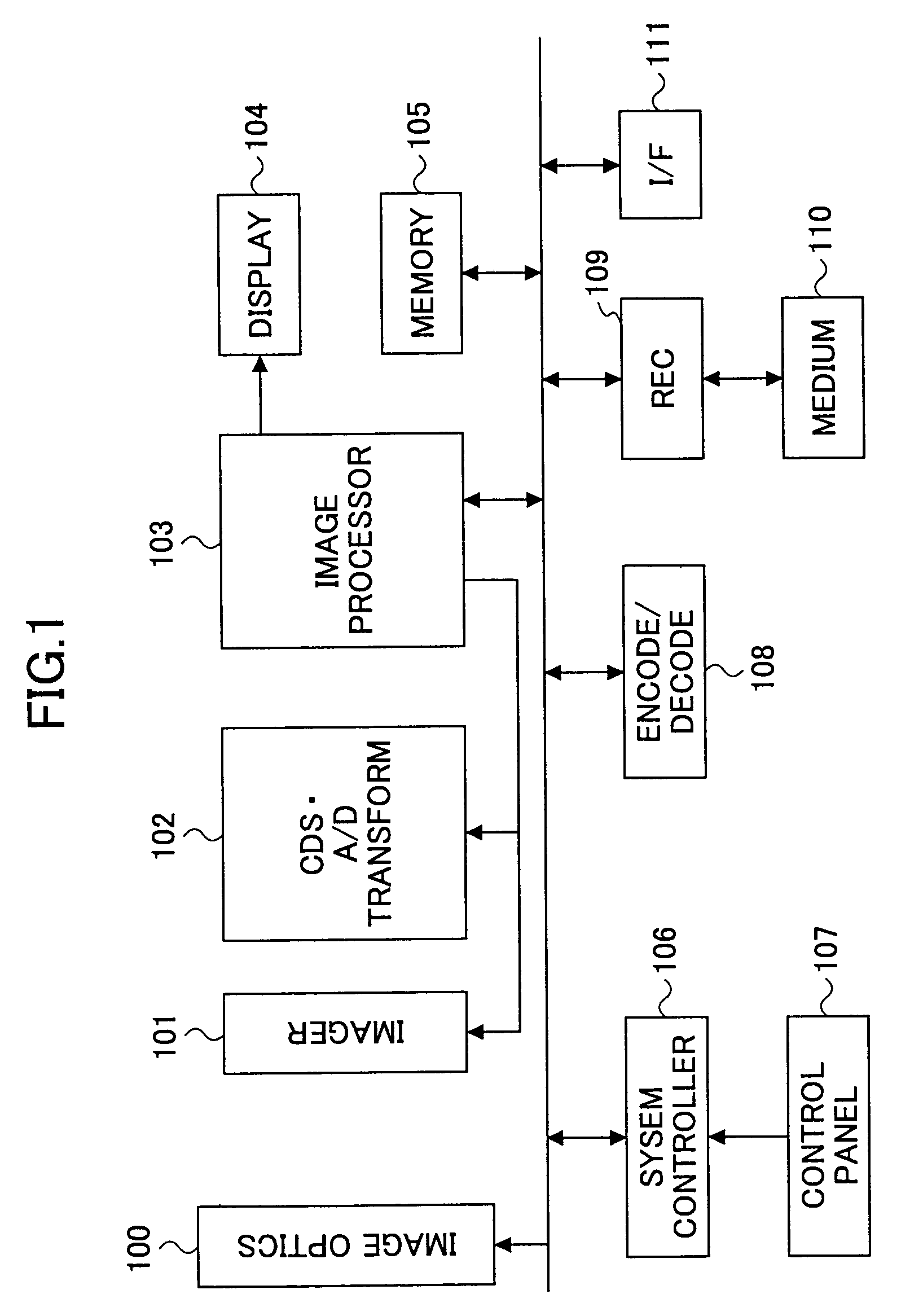
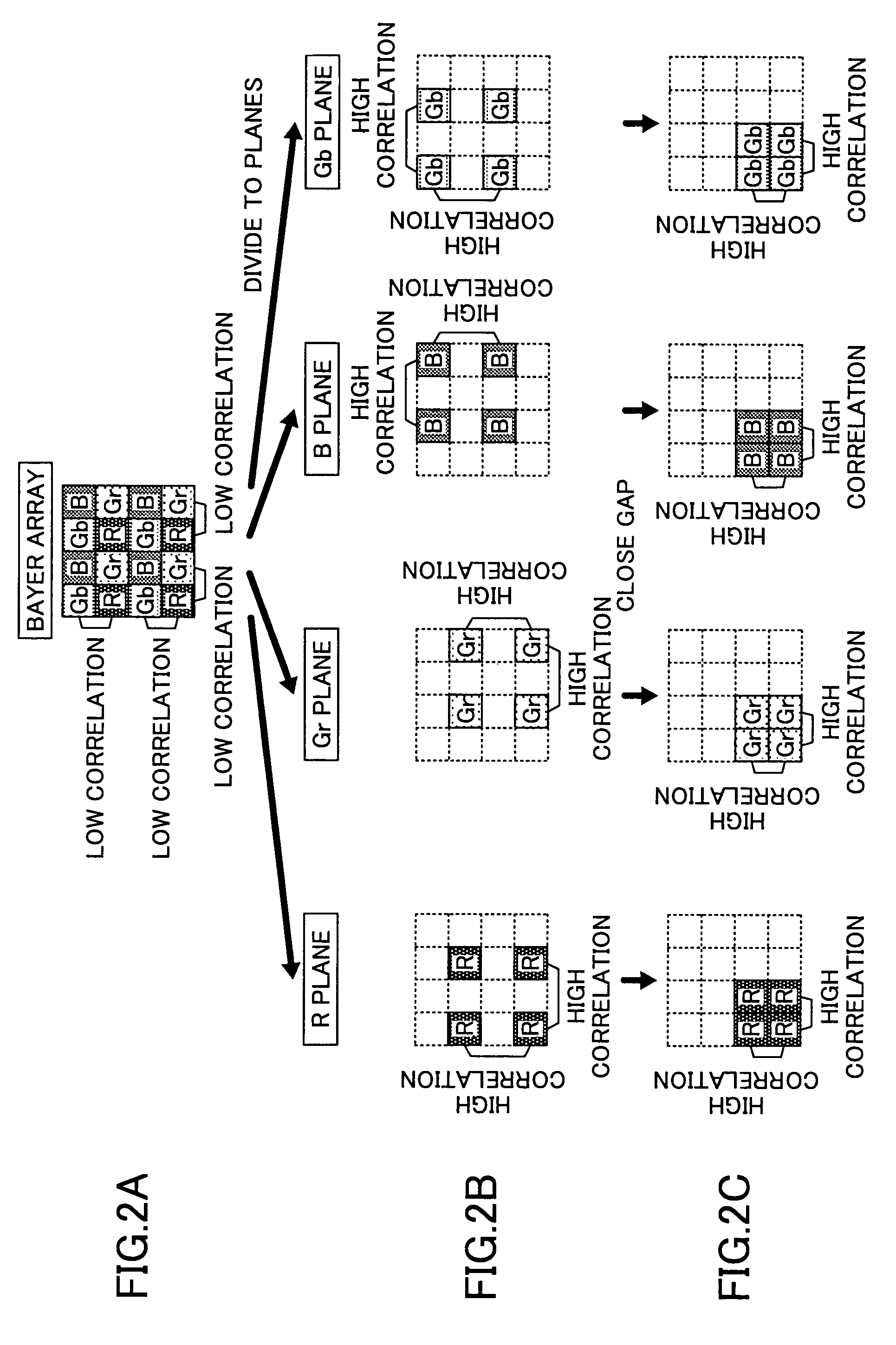
[0054]According to the present invention, high compression efficiency is achieved as compared with the case of compressing the raw image data itself because of the compression conducted for each of the color planes divided out or decomposed from the raw image data. Thereby, it should be noted that strong correlation existing between adjacent pixels in such color planes is utilized. As the encoded data thus obtained is derived directly from the raw image data, which is free from signal processing such as color interpolation processing, white balance processing, gamma correction processing, edge enhancement processing, and the like, conducted in the camera, the encoded data thus obtained is also free from the effect of such signal processing. Because of the high compression ratio, the image data obtained by one embodiment of the present invention has a compact size and the efficiency of utilization of recording medium is improved substantially when the encoded image data of the present invention is recorded on a recording medium as compared with the case of recording the raw image data itself or as compared with the case of recording the raw image data with straightforward compression.
[0055]By conducting a reversible compression for all of the color planes, it becomes possible to reproduce the image data exactly identical with the raw image data, which is free from the effect of signal processing noted above. Because of the strong correlation existing between adjacent pixels, embodiments of the present invention can achieve high compression efficiency even when such a reversible compression process is employed.
[0056]By employing reversible compression to a specific color plane, which provides a profound effect on the reproduced image quality, and applying irreversible compression to the remaining color planes, it becomes possible to reduce the file size of the obtained encoded image data while reducing, and potentially minimizing, the deterioration in the reproduced image quality.
[0057]Further, by employing irreversible compression for all of the color planes, it becomes possible to reduce the file size of the encoded image data further and the efficiency of utilization of the recording medium is improved further.
[0060]By using JPEG 2000 compression encoding algorithm for the compression, the degradation of image quality is suppressed in an embodiment of the present invention and high efficiency of compression is achieved at the same time even in the case of conducting reversible compression. Further, by conducting post quantization process, it becomes possible to adjust the compression ration without conducting a recompression process. Thereby, the compression can be achieved more easily with a target compression ratio.
[0059]By constructing the imaging device such that the user can specify the compression ratio, it becomes possible to conduct image processing according to the object of the picturing. Alternatively, the compression ratio can be set automatically by extracting information about setting of the compression ratio from the raw image data.
[0060]By using JPEG 2000 compression encoding algorithm for the compression, the degradation of image quality is suppressed in an embodiment of the present invention and high efficiency of compression is achieved at the same time even in the case of conducting reversible compression. Further, by conducting post quantization process, it becomes possible to adjust the compression ration without conducting a recompression process. Thereby, the compression can be achieved more easily with a target compression ratio.

Problems solved by technology

On the other hand, such a row image data recording mode has a drawback in that the amount of the image data to be stored in the recording medium becomes enormous.
In case the imager has three million pixels, for example, the image data for a single picture may be several megabytes or more, and the efficiency of using the recording medium is degraded seriously.
In the case of the technology described in the foregoing Japanese Laid-Open Patent Application 2002-516540, op. cit., too, there is conducted a processing for calculating the R-G and B-G difference signals, and thus, problems arise that are similar to the case of signal processing conducted inside the camera as noted above.

Method used


Image

  • Imaging device, image processing method, and recording medium
  • Imaging device, image processing method, and recording medium
  • Imaging device, image processing method, and recording medium

Examples


Embodiment Construction

[0028]Accordingly, one embodiment of the present invention provides an imaging device wherein the foregoing problems are eliminated.

[0029]In the case of the technology described in the foregoing Japanese Laid-Open Patent Application 2002-516540, op. cit., too, there is conducted a process for calculating the R-G and B-G difference signals, and thus, there arises problems similar to the case of signal processing conducted inside the camera as noted above.

[0030]Another and more specific embodiment of the present invention provides an imaging device of the type that generates an image with color decomposition, where the image data is compressed efficiently and simultaneously without undergoing the influence of the signal processing conducted inside the imaging device.

[0031]Another embodiment of the present invention provides a color imaging device that includes an imager that generates an image with color decomposition, where the imager produces raw image data as a result of generating...


PUM


Abstract

An image processing method includes obtaining raw image data of an object by generating the object by an imager that generates an image of the object with color decomposition, decomposing the raw image data into a plurality of color planes such that each of the color planes comprises pixel information of a color pertinent to the color plane, and compressing data of each color plane.

Description

[0001]The present application claims priority to the corresponding Japanese Application No. 2002-286044, filed on Sep. 30, 2002, the entire contents of which are hereby incorporated by reference.BACKGROUND OF THE INVENTION[0002]The present invention relates to imaging devices for generating color images such as digital still cameras, digital video cameras, stand-alone type image scanners, image scanners integrated to copying machines, and the like. More particularly, the present invention relates to an imaging device that uses an imager of the type of that generates an image with color decomposition.[0003]A CCD-type or MOS-type imager (imaging element) for use in digital still cameras or digital video cameras generally has color filters for color decomposition on an imaging surface thereof and captures an image with color decomposition. Thus, each pixel therein provides information about only one color component. Thus, generally conduct color interpolating processing is performed fo...

Claims


Application Information

Patent Timeline
IPC IPC(8): G06K9/36G06K9/00H04N9/07G06K9/46H04N1/41H04N1/64
CPCH04N1/648H04N19/186H04N19/63
Inventor IKEBE, KEIICHIINOUE, TAKAOTAKAHASHI, AKIRAMAKI, TAKASHIKODAMA, TAKUYAMASHIRO, IKUKOYANO, TAKANORIKOYAMA, TAKESHIAOKI, SHINSAKUYAMA, HIROYUKI
Owner RICOH KK
Learn More