Method for planning a vehicle diagnosis

a vehicle and diagnostic technology, applied in the direction of machines/engines, electrical control, instruments, etc., can solve the problems of increasing fuel consumption, increasing energy consumption, economic counterproductive, etc., and destroying the environmen

Active Publication Date: 2015-07-23
ROBERT BOSCH GMBH
View PDF16 Cites 18 Cited by
  • Summary
  • Abstract
  • Description
  • Claims
  • Application Information

AI Technical Summary

Benefits of technology

[0018]In an alternative development of the present invention, the indicated method includes the step of reading out the route to be traveled from a navigation device, and estimation of the operating characteristic of the vehicle based on information provided by the navigation device concerning the route to be traveled. This information provided by the navigation device can originate for example from environmental data or traffic data, such as that distributed for example via the Traffic Message Channel service. Thus, for example given a foreseeable traffic jam on a street traveled by the vehicle, vehicle diagnoses can be avoided that would presuppose a high-speed operation of the internal combustion engine of the vehicle. It is also possible to request from the navigation device altitude data, climate data, or any other data concerning the route to be traveled that can be provided by the navigation device.
[0019]In another alternative development, the indicated method includes the steps of writing a vehicle log based on a route traveled by the vehicle before traveling the route to be traveled, and estimating the operating characteristic of the vehicle on the route to be traveled by the vehicle based on the written vehicle log. Using the vehicle log, for example route-dependent load data of the internal combustion engine of the vehicle can be noted and used for planning the vehicle diagnosis. If, due to a particular driving behavior of the driver, for example because he commutes daily between his residence and his place of work, it turns out that after a particular number of kilometers traveled a particular load state is always achieved, e.g. because the driver has to stop at a traffic light, this can effectively be used in the planning of the vehicle diagnosis in the vehicle.

Problems solved by technology

However, if after a longer period of operation an operating characteristic suitable for the vehicle diagnosis does not arise, the vehicle could be forced into the operating characteristic suitable for carrying out the vehicle diagnosis; however, this would result in correspondingly increased energy consumption and thus correspondingly increased fuel consumption, which is not only economically counterproductive but also damaging to the environment.

Method used


Image

  • Method for planning a vehicle diagnosis
  • Method for planning a vehicle diagnosis
  • Method for planning a vehicle diagnosis

Examples


Embodiment Construction

[0032]In the Figures, elements having identical or comparable functions are provided with identical reference characters, and are described only once.

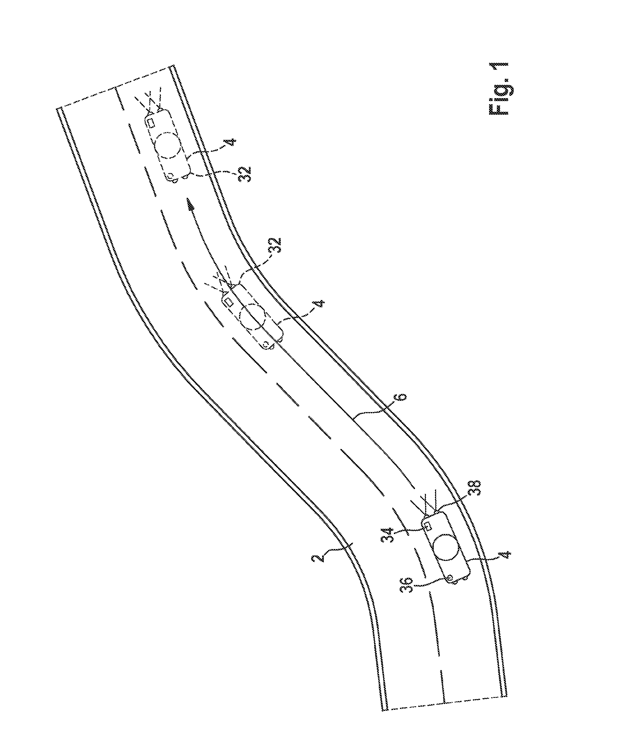
[0033]Reference is made to FIG. 1, which shows a schematic representation of a vehicle 4 traveling on a roadway 2.

[0034]Vehicle 4 moves along a route 6 on roadway 2. At an assumed first point in time, vehicle 4 is located at a position on roadway 2 at which vehicle 4 is shown in solid lines in FIG. 1. In addition, vehicle 4 is shown in FIG. 1 with dotted lines at a second and at a third position at which, seen from the first point in time, it will be situated at a second and third point in time in the future.

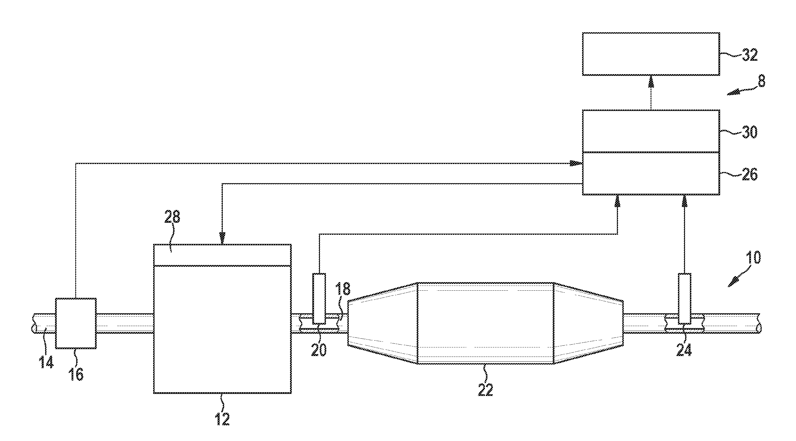
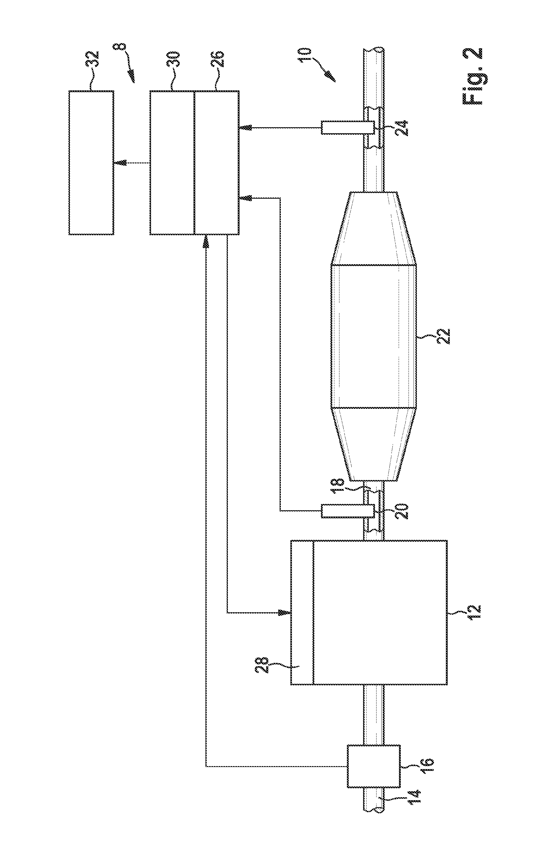
[0035]In order to ensure error-free operation of vehicle 2, so-called on-board tests, or OBD tests, are prescribed by law in order to timely recognize an exhaust-gas-related malfunctioning of vehicle 2 and to prevent environmental damage due to the malfunctioning of vehicle 2. Such OBD tests are defined for example by the Californi...


PUM


Abstract

A method for planning a vehicle diagnosis in a vehicle includes: estimation of an operating characteristic of the vehicle on a route to be traveled by the vehicle; and planning of the vehicle diagnosis based on a probability that the estimated operating characteristic of the vehicle will correspond to an operating characteristic suitable for the vehicle diagnosis.

Description

BACKGROUND OF THE INVENTION[0001]1. Field of the Invention[0002]The present invention relates to diagnostic systems for vehicles and to methods for planning a vehicle diagnosis.[0003]2. Description of the Related Art[0004]From published German patent application document DE 10 2009 045 376 A1, a method is known for diagnosing the dynamic behavior of an exhaust gas sensor. The disclosed diagnostic method is part of an on-board diagnosis, or OBD, that monitors all systems that influence the exhaust gas in a vehicle during driving operation. Errors that occur can be stored in a storage device and can be read out via standardized interfaces when there is a technical check of the vehicle. In addition, errors that occur can be indicated to the driver of the vehicle via a warning light.BRIEF SUMMARY OF THE INVENTION[0005]According to a first aspect of the present invention, a method is provided for the temporal planning of a vehicle diagnosis in a vehicle, having the following steps:[0006]...

Claims


Application Information

Patent Timeline
Patent Type & Authority Applications(United States)
IPC IPC(8): G07C5/08G01C21/34
CPCG01C21/34G07C5/0808B60W50/0097B60W50/04F01N3/10F01N11/00Y02T10/84F01N2900/12F02D41/22F02D41/1495F02D2200/702F02D2200/701B60W2050/041B60W2552/00B60W2554/00B60W2556/50Y02T10/40B60W2556/10Y02A50/20B60W50/0205B60W2554/406
Inventor SCHNURR, RAINERSCHULZ, UDOFISCHER, UTA
Owner ROBERT BOSCH GMBH
Why Eureka
Try Eureka