Transformer hydrogen gas monitoring system, device, and method

a technology of hydrogen gas monitoring system and transformer, which is applied in the direction of transmission system, resistance/reactance/impedence, instruments, etc., can solve the problems of aging failure of transformers, high maintenance costs, and longer preventive diagnosis cycle of transformers, so as to simplify reduce the cost of the preventive diagnosis process on a large number of transformers

Active Publication Date: 2022-02-08
KOREA ELECTRIC POWER CORP
View PDF18 Cites 0 Cited by
  • Summary
  • Abstract
  • Description
  • Claims
  • Application Information

AI Technical Summary

Benefits of technology

[0020]As set forth above, according to an exemplary embodiment in the present disclosure, since the transformer hydrogen gas monitoring system, device and method according to an exemplary embodiment in the present disclosure may perform the gas analysis without extracting the gas in the transformer, the cost of the preventive diagnosis process on a large number of transformers may be reduced, and the preventive diagnosis process may be simplified.
[0021]The simplification of the preventive diagnosis process may lead to shortening of the transformer preventive diagnosis cycle, and may be the basis for establishing the environment in which the manager may monitor the gas in the transformer in real time.
[0022]Therefore, the transformer hydrogen gas monitoring system, device and method according to an exemplary embodiment in the present disclosure may collectively collect the hydrogen concentration information from the large number of transformers, and may support accurate transformer fault sign diagnosis and management through analysis of the collected hydrogen concentration information.

Problems solved by technology

Such a method is expensive for maintenance, such as filter replacement, which leads to longer transformer preventive diagnosis cycle.
The aging failure of the transformer may frequently occur during the transformer preventive diagnosis cycle.

Method used


Image

  • Transformer hydrogen gas monitoring system, device, and method
  • Transformer hydrogen gas monitoring system, device, and method
  • Transformer hydrogen gas monitoring system, device, and method

Examples


Embodiment Construction

[0027]Exemplary embodiments of the present invention will be described in detail with reference to the accompanying drawings. It should be appreciated that various exemplary embodiments of the present invention are different from each other, but do not have to be exclusive. For example, specific shapes, structures, and characteristics described in the present specification may be implemented in another exemplary embodiment without departing from the spirit and the scope of the present invention in connection with an exemplary embodiment. In addition, it should be understood that a position or an arrangement of individual components in each disclosed exemplary embodiment may be changed without departing from the spirit and the scope of the present invention. Therefore, a detailed description described below should not be construed as being restrictive. In addition, the scope of the present invention is defined only by the accompanying claims and their equivalents if appropriate. Simi...


PUM

PropertyMeasurementUnit
resistance valueaaaaaaaaaa
variable resistanceaaaaaaaaaa
concentrationaaaaaaaaaa

Abstract

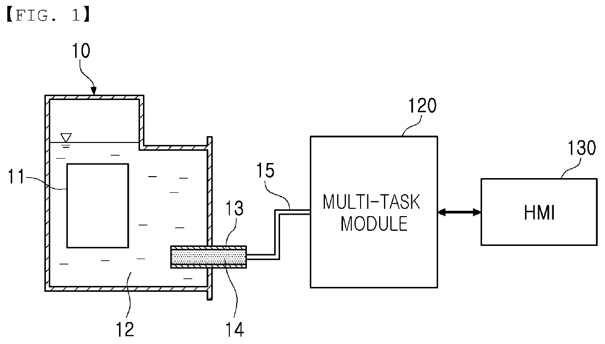
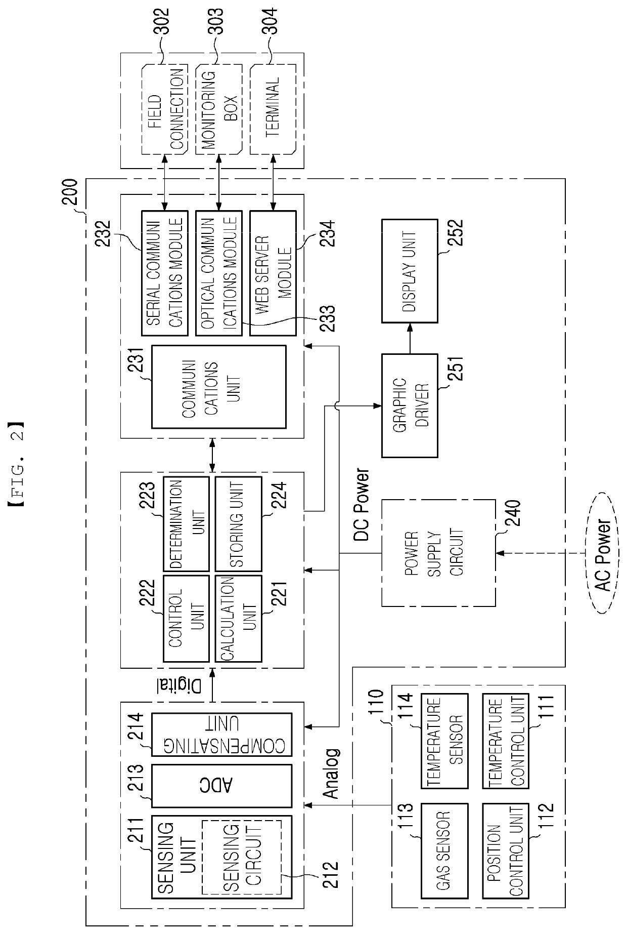
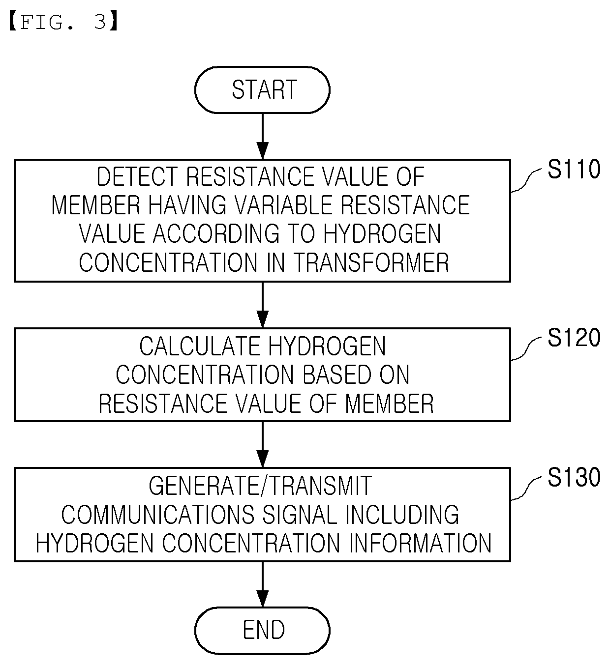
A transformer hydrogen gas monitoring system according to an embodiment of the present invention may comprise: a sensor module, which is disposed to allow at least a part thereof to meet hydrogen gas in a transformer and measures a resistance value of a member having a variable resistance value according to a hydrogen concentration in the transformer; and a multi-task module for receiving a sensing result of the sensor module, generating hydrogen concentration information corresponding to resistance value information included in the sensing result, and remotely transmitting information corresponding to the generated hydrogen concentration information.

Description

CROSS REFERENCE TO RELATED PATENT APPLICATION(S)[0001]This application claims the benefit under 35 U.S.C. Section 371, of PCT International Application No. PCT / KR2017 / 008994, filed on Aug. 18, 2018, which claimed priority to Korean Patent Application No. KR 10-2017-0030662, filed on Mar. 10, 2017, the disclosures of which are hereby incorporated by the references.TECHNICAL FIELD[0002]The present disclosure relates to transformer hydrogen gas monitoring system, device and method.BACKGROUND ART[0003]As an aging failure phenomenon in transformers installed in the field has increased recently, the necessity of establishing a preventive diagnosis system in preparation for aging failure is increasing. A transformer preventive diagnosis may be performed through gas chromatograph (GC) in the transformer.[0004]Conventional transformer preventive diagnosis was performed by a method of extracting gas from the transformer through a filter (membrane) and analyzing the extracted gas. Such a metho...

Claims


Application Information

Patent Timeline
Patent Type & Authority Patents(United States)
IPC IPC(8): G01N27/04G01N33/28G01N33/00G01R27/02H01F27/40G01R31/12H01F27/14G01R31/62G08C17/02
CPCG01R31/62G01N27/04G01N33/005G01N33/2841G01R27/02G01R31/12G08C17/02H01F27/14H01F27/402H01F2027/404G01N27/127G01R31/1281
Inventor KIM, SEOK-KONHAN, JEONG-YEOLLEE, YOU-JINKIM, TEA-KYUNAN, YONG-HOJANG, BYUNG-TAECHOI, JONG-KEELEE, NAM-HOKIM, NAM-DAE
Owner KOREA ELECTRIC POWER CORP
Why Eureka
Try Eureka