

Introduction device
a technology of introduction device and curving portion, which is applied in the direction of mechanical control device, instrument, application, etc., can solve the problems of difficulty for the operator to recognize the curving state of the curving portion, and it is difficult to recognize whether the current rotational position is 60 degrees or 420 degrees
- Summary
- Abstract
- Description
- Claims
- Application Information
AI Technical Summary
Benefits of technology
Problems solved by technology
Method used
Image

Examples
first embodiment
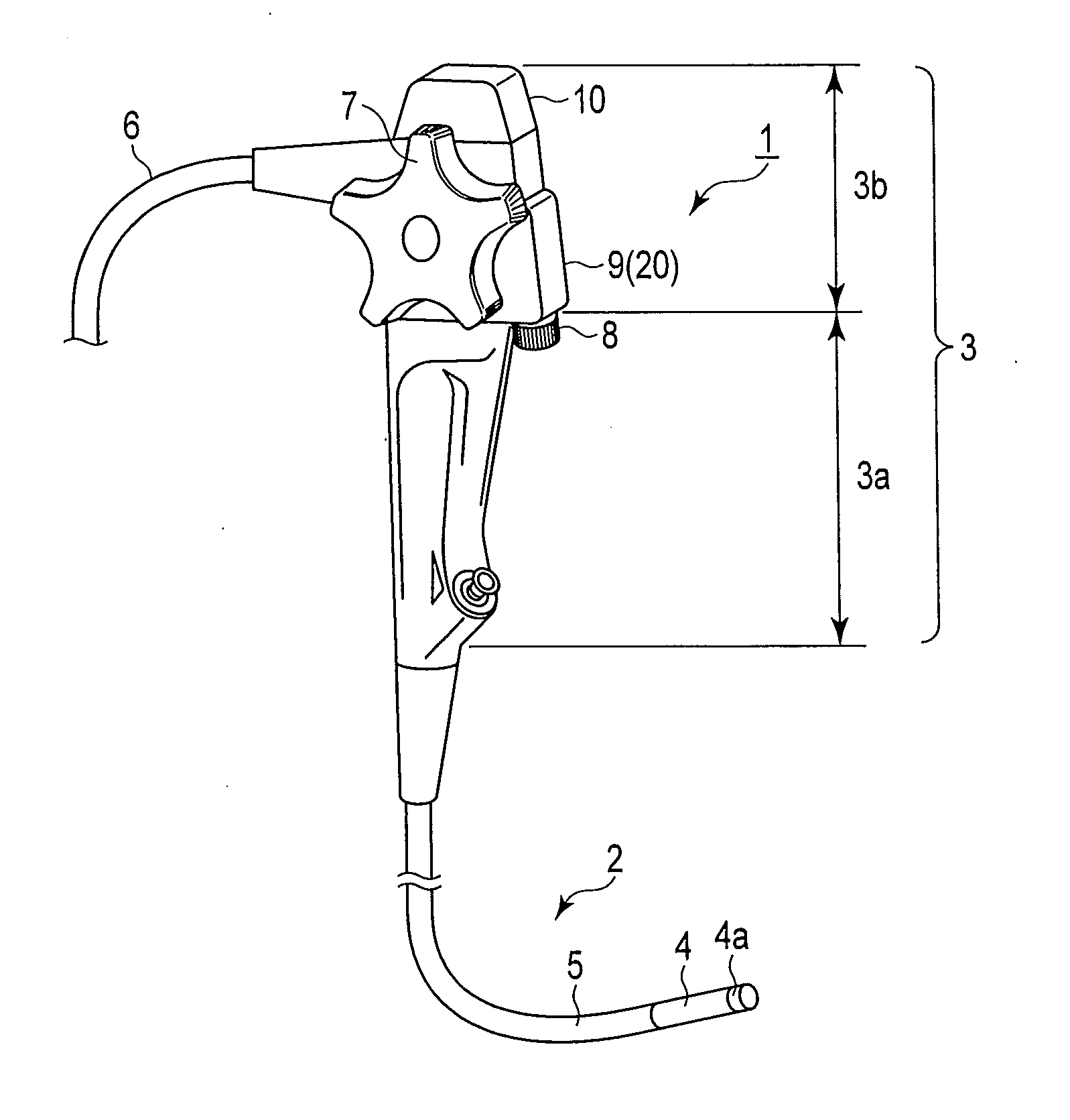
[0027]FIG. 1 is a diagram showing the exterior configuration of an endoscopic body according to a first embodiment.
[0028]In the example described according to the present embodiment, an introduction device 1 is applied to a medical endoscopic device intended for observation in a lumen or a body cavity of a living body, or an industrial endoscopic device for observation in a pipe or an engine.
[0029]The introduction device 1, that is, the endoscopic device roughly has an insertion portion 2 to be inserted into the body cavity from the distal side, an operation portion 3 coupled to the proximal side of the insertion portion 2, and a universal cord 6 including a light guide and a signal cable extending from the operation portion 3.
[0030]The insertion portion 2 comprises a flexible tube 5 which curves flexibly, a curving potion 4 which is curved in up-down (UD) and right-left (RL) directions relative to an insertion direction, and a distal portion 4a which is provided at the distal end o...
second embodiment
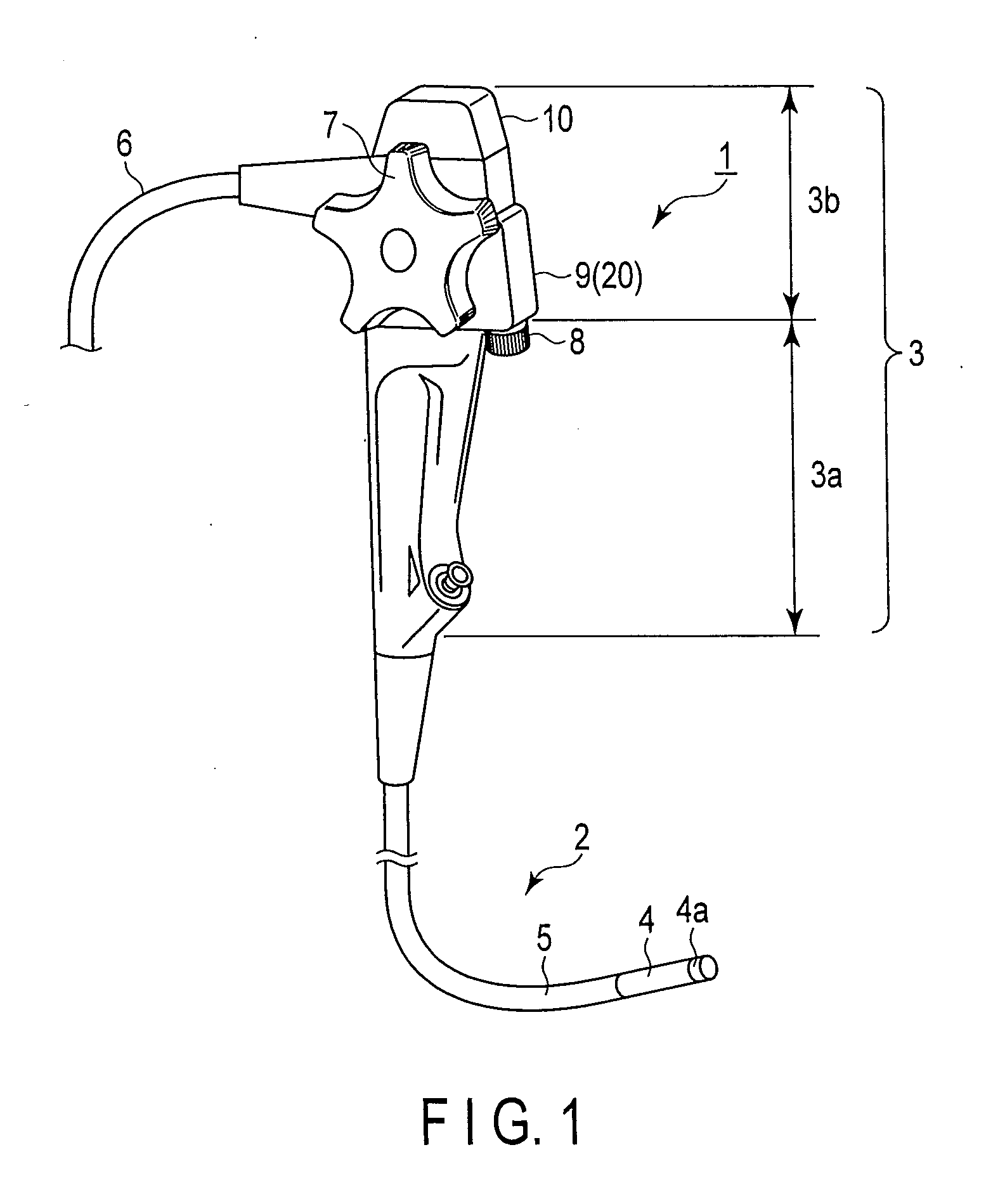
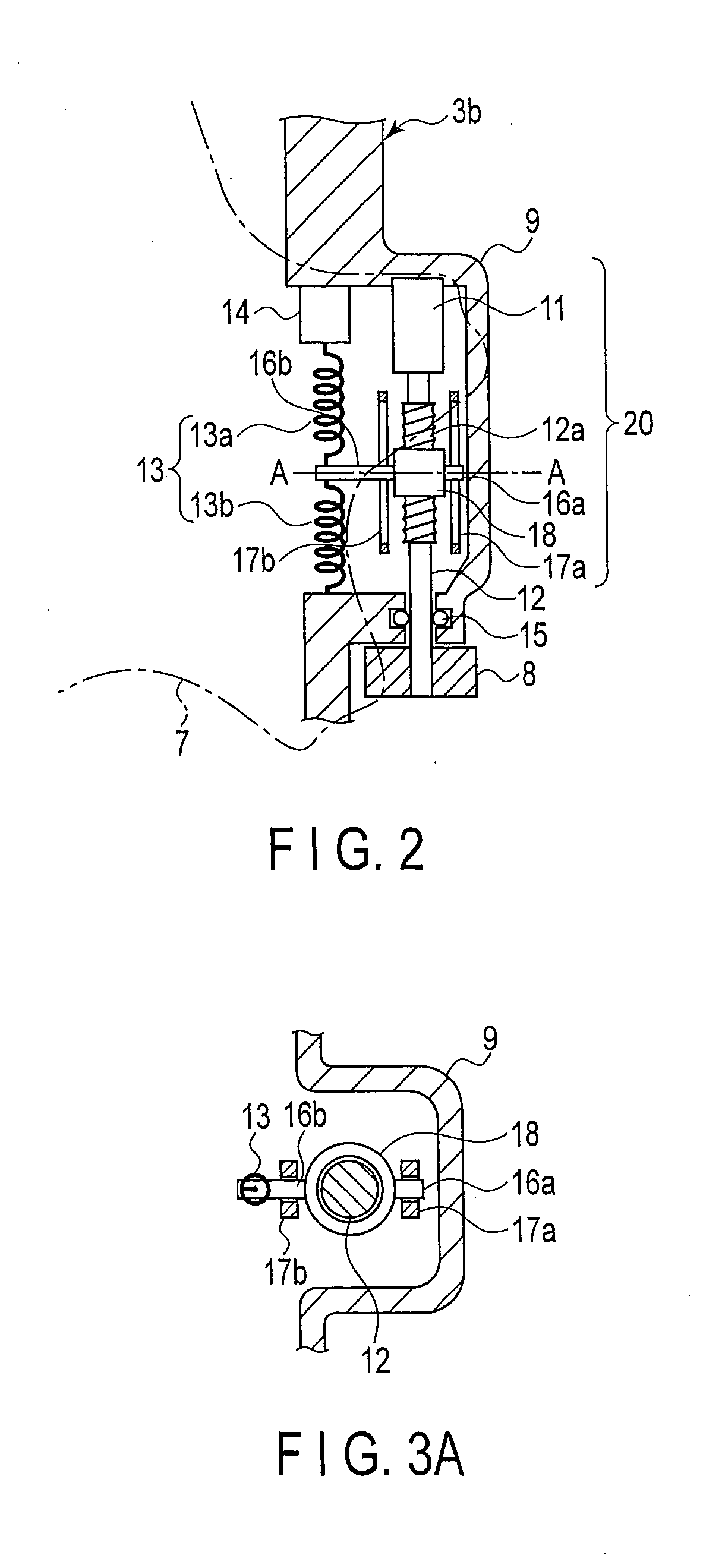
[0051]FIG. 4 is a diagram showing the conceptual configuration of an input unit housed in an operation portion according to a second embodiment. Components in the present embodiment equivalent to those in the first embodiment described above are provided with the same reference signs, and are not described. Although not shown, an operation portion 3 according to the present embodiment includes the grip portion 3a and the operation portion body 3b that have been described above. The operation portion body 3b also has a UD knob (rotation knob) 7 and an RL operation dial 8.
[0052]An input unit 20 according to the present embodiment comprises an operator and a neutral return mechanism. The operator comprises the RL operation dial 8, a drive shaft 12, and a potentiometer 11. The neutral return mechanism comprises a screw shaft 12a, a nut portion 18, guide shafts 16a and 16b, guide portions 17a and 17b, and springs 13 (13a, 13b, 13c, and 13d) attached to long holes of the guide portions 17...
third embodiment
[0057]FIG. 5 is a diagram showing the conceptual configuration of an input unit housed in an operation portion according to a third embodiment. FIGS. 6A, 6B and 6C are diagrams showing a spring fitted to a rotary dive shaft when viewed from the direction of B-B in FIG. 5. FIG. 6D is a diagram showing a configuration example for setting a neutral return range. Components in the present embodiment equivalent to those in the first embodiment described above are provided with the same reference signs, and are not described. Although not shown, an operation portion 3 according to the present embodiment includes the grip portion 3a and the operation portion body 3b that have been described above. The operation portion body 3b also has a UD knob (rotation knob) 7 and an RL operation dial 8.
[0058]An input unit 20 according to the present embodiment comprises an operator and a neutral return mechanism. The operator comprises the RL operation dial 8, a drive shaft 12 erected on the RL operati...
PUM
 Abstract
Description
Claims
Application Information