Electric taxi system with speed control (ETSSC)

Active Publication Date: 2015-07-30
HONEYWELL INT INC
View PDF8 Cites 26 Cited by
  • Summary
  • Abstract
  • Description
  • Claims
  • Application Information

AI Technical Summary

Benefits of technology

[0006]In one aspect of the present invention, an electric taxi system (ETS) for an aircraft may comprise: a ground speed sensor; a speed selection unit; a speed computer coupled to the ground speed sensor and to the spe

Problems solved by technology

A significant amount of fuel may be burned by the engines during a typical aircraft taxi profile before and after each flight.
In that regard, engine-thrust taxiing may be considered inefficient and may contribute to high fuel cos

Method used


Image

  • Electric taxi system with speed control (ETSSC)
  • Electric taxi system with speed control (ETSSC)
  • Electric taxi system with speed control (ETSSC)

Examples


Embodiment Construction

[0016]The following detailed description is of the best currently contemplated modes of carrying out the invention. The description is not to be taken in a limiting sense, but is made merely for the purpose of illustrating the general principles of the invention, since the scope of the invention is best defined by the appended claims.

[0017]Various inventive features are described below that can each be used independently of one another or in combination with other features.

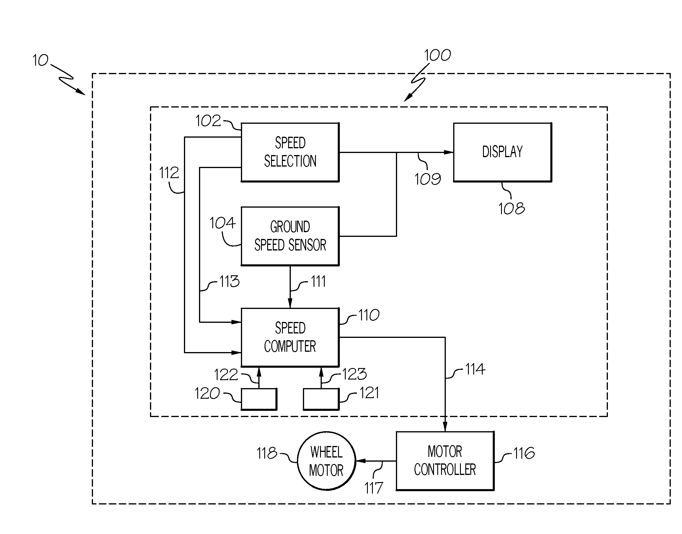
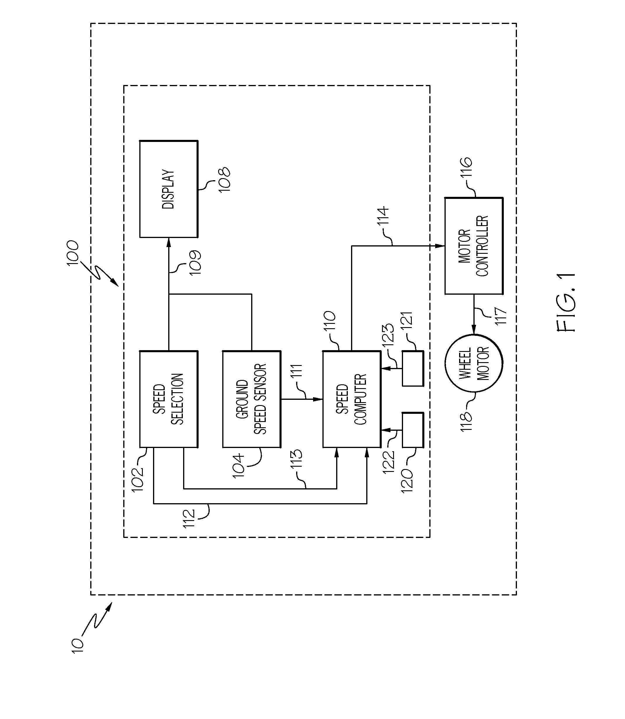
[0018]The present invention generally provides an ETS for an aircraft. The ETS may employ a ground speed control system that can be retrofitted into an aircraft along with the ETS. More particularly the ground speed control system may display both commanded and actual speed and may have the capability of holding a commanded speed. Moreover, the speed control systems may employ pilot interfaces that are similar to those with which pilots are presently familiar.

[0019]Referring now to FIG. 1, an exemplary embodiment ...


PUM


Abstract

An electric taxi system (ETS) for an aircraft may include a ground speed sensor, a speed selection unit and a speed computer coupled to the ground speed sensor and to the speed selection unit. The speed computer may produce a speed error signal. A motor controller coupled to a wheel motor may control speed of the wheel motor responsively to the speed error signal.

Description

BACKGROUND OF THE INVENTION[0001]The present invention generally relates to aircraft electric taxi systems (ETS). More particularly, the invention relates to control of ground speed of an aircraft as the aircraft is taxied by the ETS.[0002]A typical aircraft may taxi to and from runways with thrust force developed by its engines that are optimized for high speed at altitude operation not ground idle. A significant amount of fuel may be burned by the engines during a typical aircraft taxi profile before and after each flight. In many cases, the main engines may provide more motive force than is required to complete a successful taxi profile and brakes have to be applied to slow the aircraft down. The actual speed is determined by engine thrust, aircraft weight, rolling friction and atmospheric conditions. In that regard, engine-thrust taxiing may be considered inefficient and may contribute to high fuel costs and ground level emissions.[0003]Nevertheless, many existing aircraft and m...

Claims


Application Information

Patent Timeline
IPC IPC(8): B64C25/40B64C19/00
CPCB64C19/00B64C25/405B64D31/04Y02T50/80
Inventor DE MERS, ROBERT E.OLOFINBOBA, OLUKAYODEHUGHES, KEITHOTT, JOSEPH
Owner HONEYWELL INT INC
Why Eureka
Try Eureka