Disc Brake for a Motor Vehicle, Comprising a Plastically Deformable Restoring Spring, and Restoring Spring

a technology of disc brake and restoring spring, which is applied in the direction of axially engaging brakes, braking systems, applications, etc., can solve the problems of inability to predict whether the plastic deformation curve always corresponds precisely to the actual wear state, and the remaining elastic deformation component no longer provides an adequate restoring movement, so as to achieve reliable wear compensation and constant restoring behaviour

Active Publication Date: 2015-07-30
LUCAS AUTOMOTIVE GMBH
View PDF10 Cites 21 Cited by
  • Summary
  • Abstract
  • Description
  • Claims
  • Application Information

AI Technical Summary

Benefits of technology

[0006]In contrast to this it is a feature of the present invention to provide a disc brake of the type described in the introduction, the restoring spring of which provides reliable wear compensation combined with constant restoring behaviour.

Problems solved by technology

It has however been shown that such solutions do not exhibit reliable behaviour during wear compensation.
In particular, it is difficult to predict whether a plastic deformation of the spring curve always corresponds precisely to the actual wear state.
This may lead to the spring being for example overly deformed, with the result that the remaining elastic deformation component no longer provides an adequate restoring movement and residual sliding moments occur.
On the other hand it is equally possible for the spring to be insufficiently plastically deformed, with the result that it provides a greater restoring travel than is desired.
This leads to a delayed response behaviour of the brake upon renewed actuation.

Method used


Image

  • Disc Brake for a Motor Vehicle, Comprising a Plastically Deformable Restoring Spring, and Restoring Spring
  • Disc Brake for a Motor Vehicle, Comprising a Plastically Deformable Restoring Spring, and Restoring Spring
  • Disc Brake for a Motor Vehicle, Comprising a Plastically Deformable Restoring Spring, and Restoring Spring

Examples


first embodiment

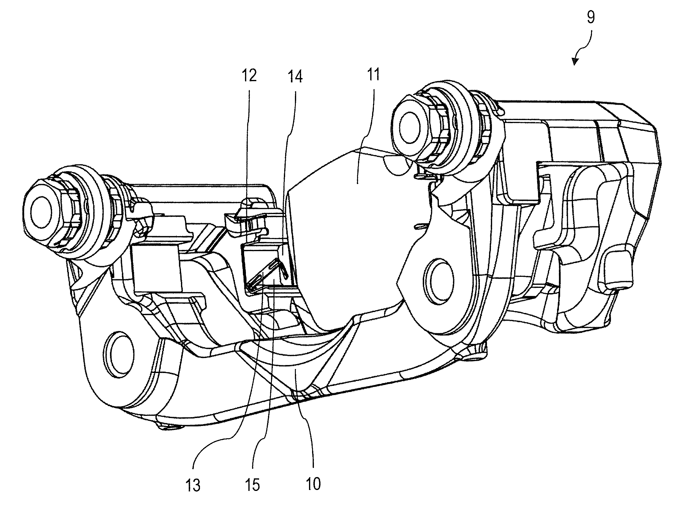
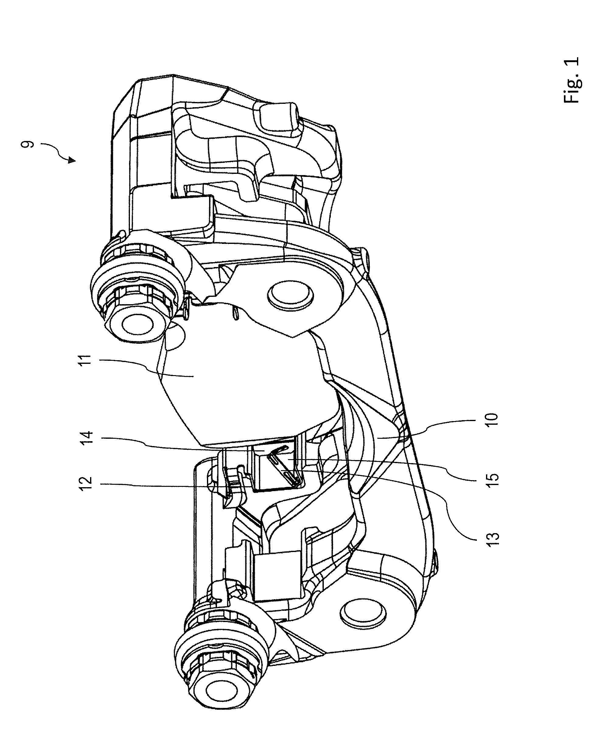
[0032]During the service period of the disc brake 9 a brake lining, which is situated on parts of the surface of the brake lining arrangement 11 facing the restoring spring 13, is eroded by wear. In order that the response behaviour of the disc brake 9 remains constant, such wear is typically compensated by means of a wear correction corresponding to the actual brake lining wear. In this case the brake lining arrangement 11 is permanently displaced forward in the direction of the restoring spring 13 and / or in actuating direction. The starting position and / or restoring position of the brake lining arrangement 11 is likewise to be adapted by means of a wear correction to the increasing brake lining wear and / or to a compensating forward displacement of the brake lining arrangement 11. This means that the starting position and / or restoring position is likewise to be changed for the purpose of wear compensation. The restoring spring 13 according to the invention solves this problem of we...

second embodiment

[0042]In the second embodiment the restoring spring 13 and the guide clip 15 are manufactured by shaping from a common, initially flat component. This flat component is represented on its own in FIG. 10 and denoted by 40. It is evident that the restoring spring 13 and guide clip 15 initially take the form of substantially elongate portions 44 and 46 of the component 40. In this case the respective portions 44 and 46 already for the most part have the basic contours and recesses in accordance with the finished combination of restoring spring 13 and guide clip 15 shown in FIGS. 7 to 9. Thus, for example the previously described recesses 34 and 36 may be seen in the portion 44.

[0043]To manufacture the unit of restoring spring 13 and guide clip 15 according to the second embodiment the flat component 40 is bent around a plurality of bending axes, the position of which may be gathered from a combined viewing of the finished shaped component shown in FIGS. 7 to 9. It is self-evident that ...

third embodiment

[0046]The bending axis z, around which the surface area portion 44 is bent relative to the portion 46, extends in this embodiment at an angle α of 45° relative to the longitudinal axis L1 of the surface area portion 44. This enables the restoring spring 13 in the third embodiment also to be aligned in the same manner relative to the guide clip 15 and the actuating direction as in the examples discussed above.

[0047]A finished shaped unit according to the third embodiment is shown in FIGS. 12 and 13. Evident once more are the obliquely extending bending axis z and the portions of the restoring spring 13 that lie adjacent thereto. In order to increase the stiffness of the region bent around the bending axis z and avoid local concentrations of stress, the restoring spring in this region is configured with a curvature 48, which is likewise produced in the course of the shaping process.

[0048]In accordance with the provisions of the patent statutes, the principle and mode of operation of t...


PUM

PropertyMeasurementUnit
angleaaaaaaaaaa
angleaaaaaaaaaa
elastic deformationaaaaaaaaaa

Abstract

A disc brake for a motor vehicle brake system and a restoring spring arranged therein, the disc brake comprising the following: a brake support which has at least one receiving region; a brake lining arrangement which has a brake lining support and a brake lining which is attached to the brake lining support and which can be brought into interaction with a brake disc in order to achieve a braking effect, wherein the brake lining arrangement is received in the at least one receiving region in a guided manner via a guiding portion formed on the brake lining support; and at least one restoring spring which engages the brake lining arrangement and biases the brake lining arrangement under elastic deformation into a starting position that does not produce a braking effect. The at least one restoring spring can be plastically deformed in order to compensate for brake lining wear. To improve the wear compensation by means of the restoring spring, rests against the brake support via a base portion and has at least one limb which is connected to the base portion via a connecting region and which is arranged at an angle relative to the base portion, the angle changing under the effect of plastic deformation as the brake lining wear increases.

Description

CROSS-REFERENCE TO RELATED APPLICATIONS[0001]This application is a national stage of International Application No. PCT / EP2013 / 067451 filed Aug. 22, 2013, the disclosures of which are incorporated herein by reference in entirety, and which claimed priority to German Patent Application No. 10 2012 016 737.7 filed Aug. 23, 2012, the disclosures of which are incorporated herein by reference in entirety.BACKGROUND OF THE INVENTION[0002]The present invention relates to a disc brake for a motor vehicle brake system, comprising a brake support which has at least one receiving region; a brake lining arrangement which has a brake lining support and a brake lining which is attached to the brake lining support and which can be brought into interaction with a brake disc in order to achieve a braking effect, wherein the brake lining arrangement is received in the at least one receiving region in a guided manner via a guiding portion formed on the brake lining support; and at least one restoring s...

Claims


Application Information

Patent Timeline
Patent Type & Authority Applications(United States)
IPC IPC(8): F16D65/06F16D65/18B21D53/36F16D65/092
CPCF16D65/06F16D65/092F16D55/02B21D53/36F16D2055/0075F16D65/183F16D65/0977F16D65/0978F16D55/226F16D65/18Y10T29/49Y10T29/49611F16D65/543
Inventor MALLMANN, MARKUS
Owner LUCAS AUTOMOTIVE GMBH
Why Eureka
Try Eureka