Thermistor device

a technology of thermistor elements and connection parts, which is applied in the field of thermometer devices, can solve the problems of cracking the body of the thermistor element, fracture the connection parts, etc., and achieve the effect of stress tolerance that is further improved

Active Publication Date: 2015-07-30
MURATA MFG CO LTD
View PDF2 Cites 4 Cited by
  • Summary
  • Abstract
  • Description
  • Claims
  • Application Information

AI Technical Summary

Benefits of technology

[0007]Therefore, preferred embodiments of the present invention provide a thermistor device with further improved tolerance to stress.
[0009]The aspect mentioned above makes it possible to provide a thermistor with stress tolerance that is further improved.

Problems solved by technology

There has been a problem that this stress fractures the connection parts, or cracks the body of the thermistor element.

Method used


Image

  • Thermistor device
  • Thermistor device
  • Thermistor device

Examples


Embodiment Construction

[0024]Thermistor devices according to preferred embodiments of the present invention will be described below in great detail with reference to the drawings.

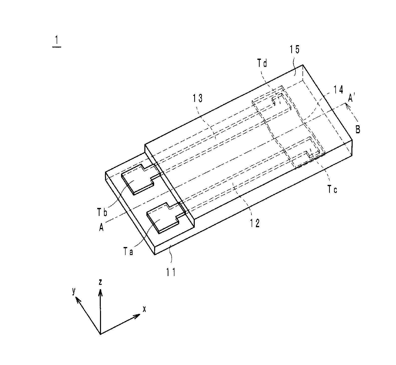
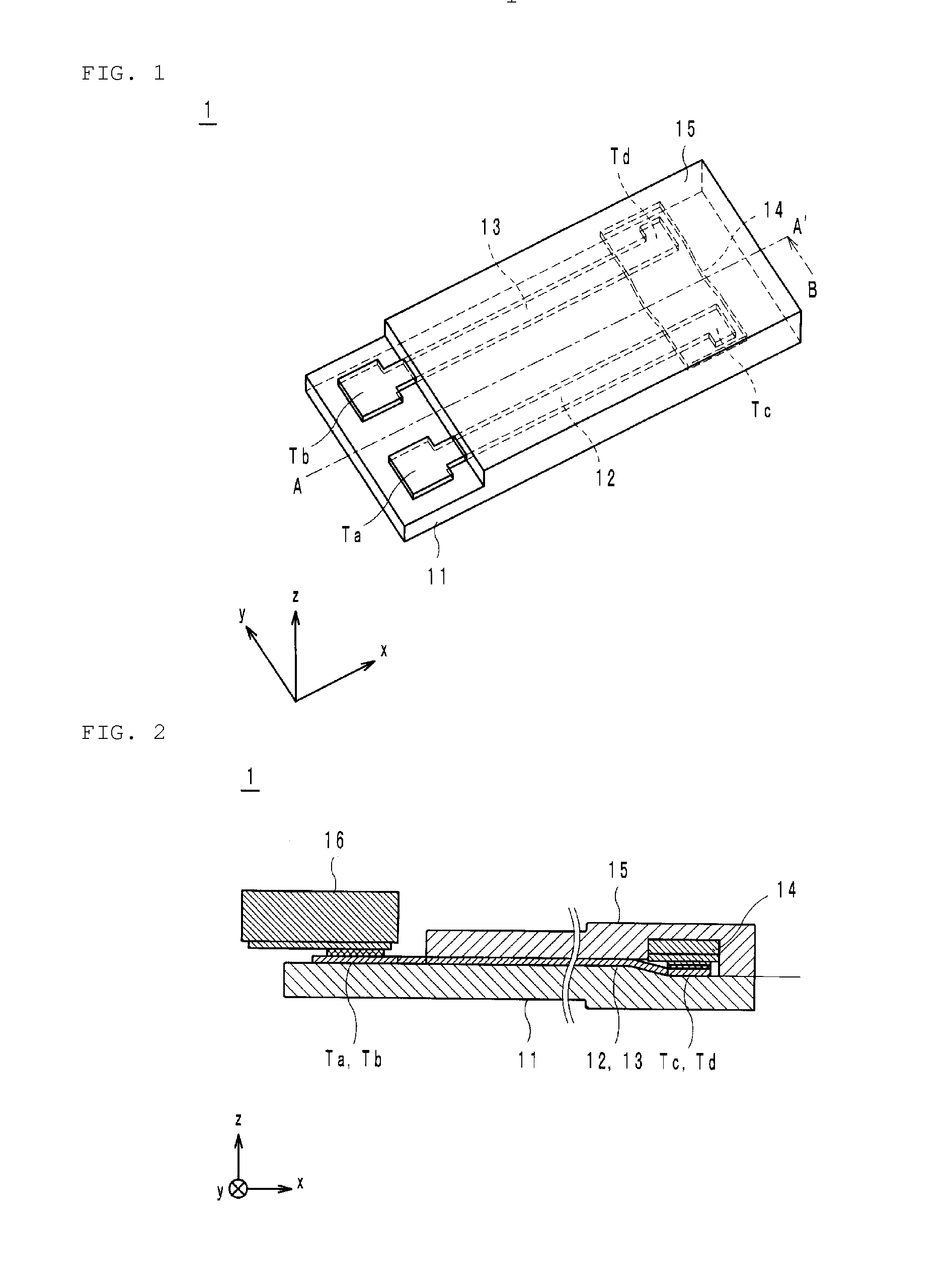
[0025]First, the x axis, y axis, and z axis will be described which are shown in some of the drawings. The x axis, y axis, and z axis, which are perpendicular to each other, indicate the horizontal direction, front-back direction, and thickness direction of the thermistor device.

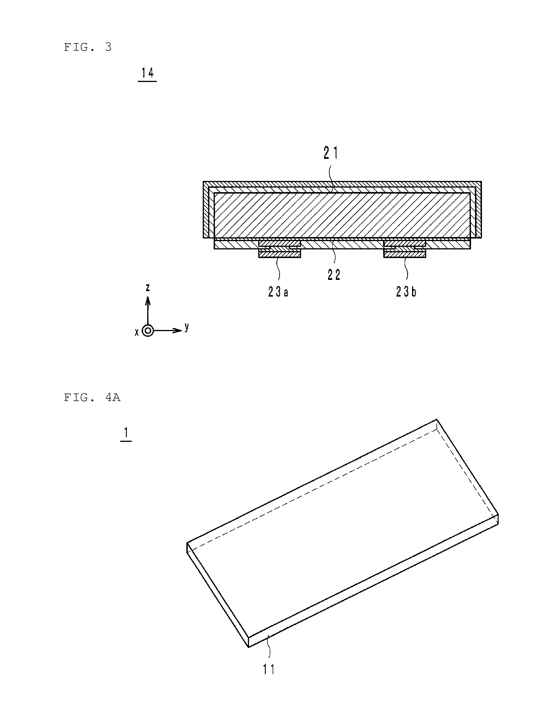
[0026]The thermistor device 1 includes, as shown in FIGS. 1 and 2, a first base material sheet 11, a first lead electrode 12, a second lead electrode 13, a flexible thermistor element 14, and a second base material sheet 15.

[0027]The first base material sheet 11 preferably has a thickness of approximately 30 μm or less in the z-axis direction, and preferably includes a rectangular or substantially rectangular principal surface parallel to the xy plane, for example. In addition, the first base material sheet 11 preferably is made of a material including on...


PUM

PropertyMeasurementUnit
thicknessaaaaaaaaaa
thicknessaaaaaaaaaa
thicknessaaaaaaaaaa

Abstract

In order to further improve stress tolerance, a thermistor device includes a first base material member made of resin, a thermistor element including a thermistor thin film provided on a metal base material and first and second external electrodes provided on the thermistor thin film, and a first lead electrode and a second lead electrode provided on a principal surface of the first base material member, and connected to the first external electrode and the second external electrode. Each of the metal base material and the thermistor thin film undergoes a deflection between the first external electrode and the second external electrode.

Description

BACKGROUND OF THE INVENTION[0001]1. Field of the Invention[0002]The present invention relates to a thermistor device including a flexible thermistor element.[0003]2. Description of the Related Art[0004]Conventionally, this kind of thermistor device is used for a temperature sensor or the like. This temperature sensor includes, as described in, for example, Japanese Patent Application Laid-Open No. 2000-266608, a heat-resistant resin sheet, two lead electrodes, a ceramic thermistor element, and an exterior sheet. The heat-resistant resin sheet is composed of polyimide of approximately 50 μm in thickness. The two lead electrodes are composed of a metallic material containing silver of approximately 10 μm in thickness. The two lead electrodes are formed by printing or the like on a principal surface of the heat-resistant resin sheet, so as to be spaced at a predetermined interval. The thermistor element is approximately 0.5 mm in thickness, and connected to one end of the two lead elec...

Claims


Application Information

Patent Timeline
Patent Type & Authority Applications(United States)
IPC IPC(8): G01K7/22H01M10/0525H01C1/012H01M2/34H01C7/00H01C1/14
CPCG01K7/22H01C7/008H01C1/14H01M2200/10H01M2/348H01M10/0525H01C1/012H01C7/02H01C7/04H01C1/1406H01C1/1413H01M10/486Y02E60/10H01M50/581
Inventor MIURA, TADAMASAKAWATA, SHUICHIYAMAMOTO, YUKI
Owner MURATA MFG CO LTD
Why Eureka
Try Eureka