Tool device

a tool and tool technology, applied in the field of tool devices, to achieve the effect of stress-tolerant design of the connection devi

Active Publication Date: 2020-10-20
C & E FEIN GMBH & CO KG +1
View PDF97 Cites 1 Cited by
  • Summary
  • Abstract
  • Description
  • Claims
  • Application Information

AI Technical Summary

Benefits of technology

[0012]The present invention has the object to design the tool device in such a manner that the torque, which has been introduced via the driving device, can be reliably absorbed.
[0111]In a preferred embodiment, the first holding device comprises a first holding shaft and the second holding device comprises a second holding shaft. Preferably, the first holding shaft and second holding shaft are arranged askew, particularly skewed to each other. In the sense of the invention, askew can be understood in that the two holding shafts are not parallel to each other on the one hand and that they do not intersect the other in the space. By such an arrangement, a particularly stress tolerant design of the connection device can be achieved.

Problems solved by technology

This limitation of the illustration is not intended to limit the possible uses of such a tool device.

Method used


Image

  • Tool device
  • Tool device
  • Tool device

Examples


Embodiment Construction

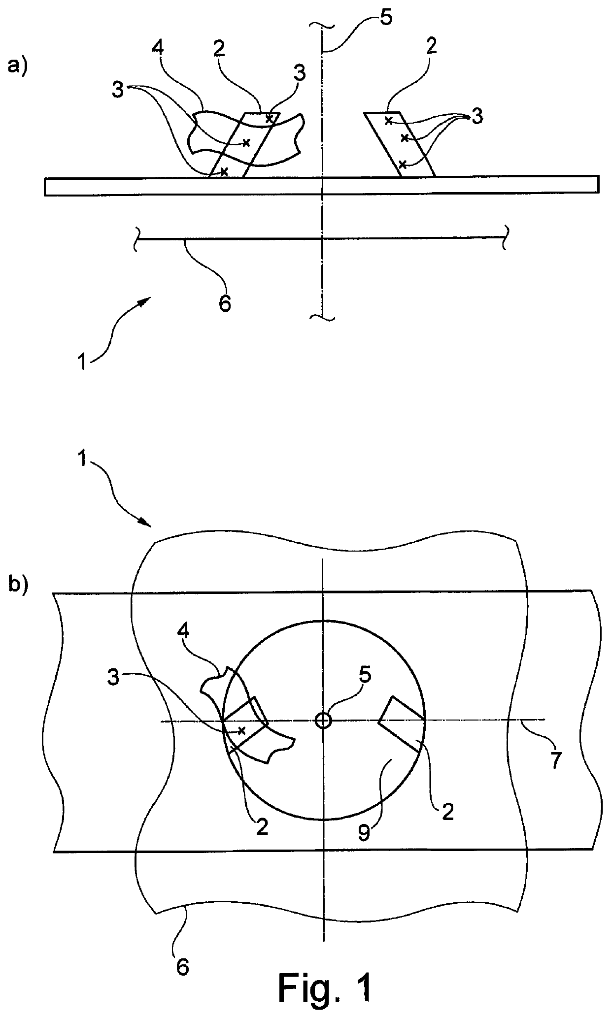
[0138]The FIG. 1 shows two views (FIG. 1a front view, FIG. 1b plan view) of a tool device 1. This tool device has two driving area regions 2. Here, a driving area region 2 has several surface points 3. A tangent plane 4 can be assigned to each of these surface points 3 in the driving area regions 2. These tangent planes 4 are inclined in regard to a radial plane 6 and in regard an axial plane 7. Here, the radial plane 6 is arranged orthogonally to a tool axis of rotation 5 and an axial plane 7 encloses the tool axis of rotation 5a. The tool device 1 is provided for a rotationally oscillating driving of a hand guided tool device (not shown). If the tool device 1 is driven by a suitable machine tool then the tool device 1 is put into a rotating oscillating motion around the tool axis of rotation 5. By the dual inclination of the driving area region 2, it can be achieved a holding free from backlash of the tool device 1 in the machine tool. This is particularly advantageous for a sawin...


PUM


Abstract

The invention relates to a tool device which is suitable for use with a machine tool, in particular a hand guided machine tool, having a driving device moving, in particular in an oscillating manner, around a driving axis. The tool device has an attachment device which allows it to be fastened on a machine tool such that its driving axis and an axis of rotation of the tool substantially coincide. The attachment device, for absorbing the driving force, has at least two driving area regions, which are spaced apart from said tool axis of rotation and each has a plurality of surface points. The tangent planes to said surface-area points are inclined in regard to an axial plane, which encloses the tool axis of rotation. Furthermore, said tangent planes are inclined regard to a radial plane which extends perpendicularly to the tool axis of rotation. This means that the torque introduced into the tool device by the machine tool, via the driving device, is reliably absorbed.

Description

CROSS REFERENCE TO RELATED APPLICATIONS[0001]This application is continuation of and claims the benefit of priority of U.S. application Ser. No. 14 / 909,204 filed on Feb. 1, 2016, which is a national stage application under 35 U.S.C. 371 and claims the benefit of PCT Application No. PCT / EP2014 / 002048 having an international filing date of 25 Jul. 2014, which designated the United States, which PCT application claimed the benefit of German Patent Application No. DE 20 2013 006 920.1 filed 1 Aug. 2013, the entire disclosures of each of which are incorporated by reference herein.FIELD OF THE INVENTION[0002]The present invention relates to a tool device, which is suited to be used with a machine tool, and in particular with a hand guided machine tool having a driving device moving around a driving axis.SUMMARY OF THE INVENTION[0003]The invention will be described below mainly using the example of a tool device, which is suited for the use with a machine tool, and in particular for the us...

Claims


Application Information

Patent Timeline
Patent Type & Authority Patents(United States)
IPC IPC(8): B23B31/10B27B5/30B23D61/00B24B23/04B27B5/32B24B45/00
CPCB27B5/30B24B45/00B23B31/10B24B45/006B24B23/04B27B5/32B23D61/006Y10T279/33B23B31/102
Inventor KLABUNDE, OLAFBLICKLE, JUERGENTHOMASCHEWSKI, WALTERBEK, FABIANDELFINI, STEFANOFELLMANN, WILLILUESCHER, BRUNOBOZIC, MILANMATHYS, THOMASGROLIMUND, DANIEL
Owner C & E FEIN GMBH & CO KG
Why Eureka
Try Eureka