
Magnetic resonance imaging system with navigator-baed motion detection

a magnetic resonance imaging and navigator-baed technology, applied in the field of magnetic resonance imaging, can solve the problems of impracticality, compromise the diagnostic quality of the resulting image, and patient motion remains an important factor, and achieve the effect of generating magnetic resonance images more quickly

Inactive Publication Date: 2015-07-30
KONINKLJIJKE PHILIPS NV
View PDF3 Cites 29 Cited by
  • Summary
  • Abstract
  • Description
  • Claims
  • Application Information

AI Technical Summary

Benefits of technology

The patent describes a system for analyzing magnetic resonance data to improve image quality. The system uses a processor to construct a matrix to evaluate the similarity of different navigator vectors. These vectors are used to guide the acquisition of magnetic resonance data. The system then uses a classification algorithm to determine the overall structure of the data and make decisions about whether to continue or discontinue the MRI protocol. This helps to improve the image and make it faster. Additionally, the system can analyze multiple slices of data to optimize the MRI protocol for each slice. Overall, this technology makes it easier to get better quality magnetic resonance images.

Problems solved by technology

Patient motion during magnetic resonance imaging (MRI) data acquisition can lead to image artifacts which compromise the diagnostic quality of the resulting images.
This is an important problem and has lead to a large number of methods which aim at reducing the impact of patient motion.
Despite these past efforts, patient motion is still an important problem today; partly because increased SNR and fast scan methods of modern magnetic resonance (MR) scanners allow imaging at higher spatial resolution which makes the experiment more sensitive to motion, partly because the proposed methods are impractical in routine clinical use.
This can be the case either because they require sensors which are too complicated and / or time consuming to connect, or because they prolong the scan duration excessively.
Other common limitations are restriction to certain anatomies / imaging sequences, negative impact on image contrast etc.

Method used


Image

  • Magnetic resonance imaging system with navigator-baed motion detection
  • Magnetic resonance imaging system with navigator-baed motion detection
  • Magnetic resonance imaging system with navigator-baed motion detection

Examples


Embodiment Construction

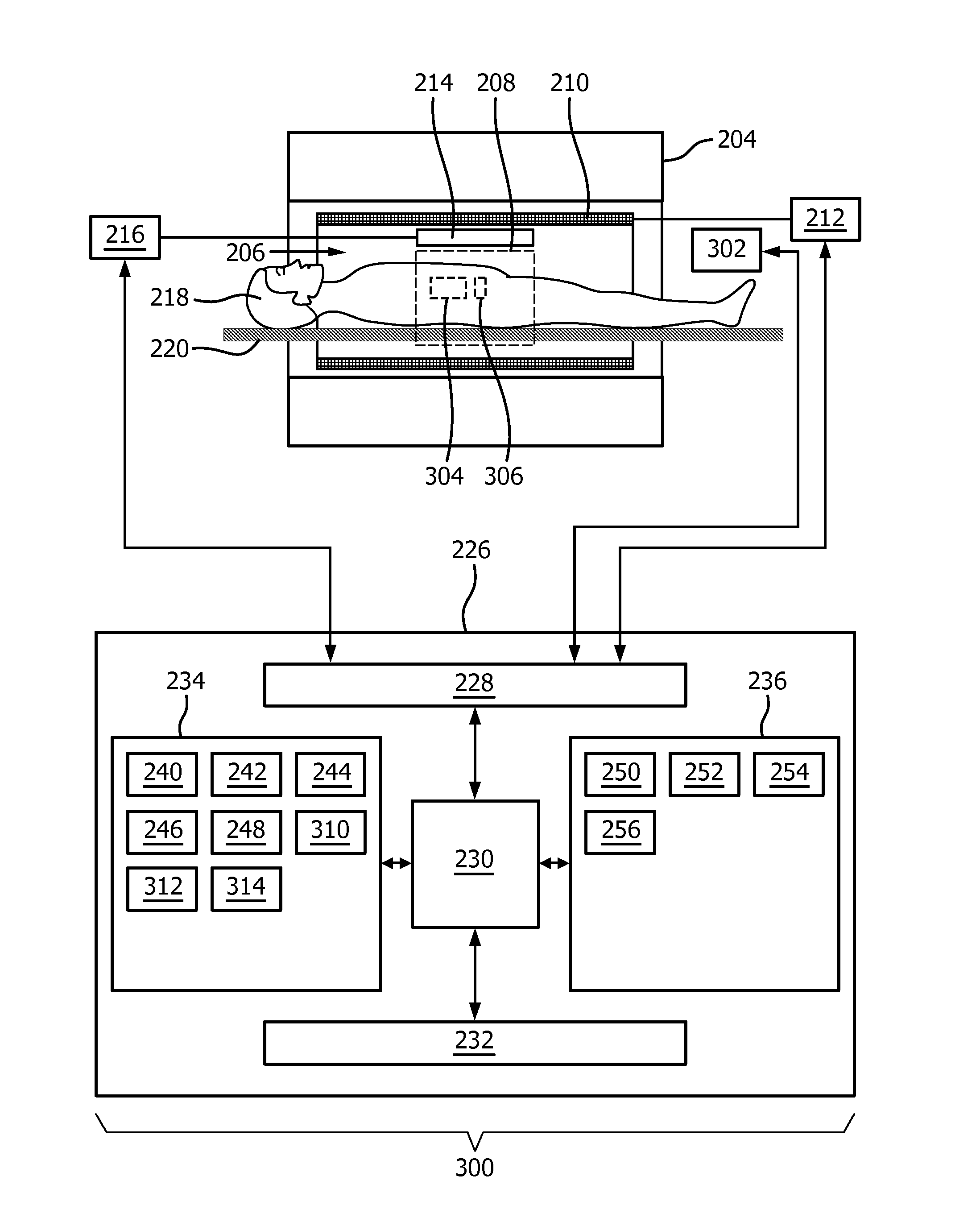
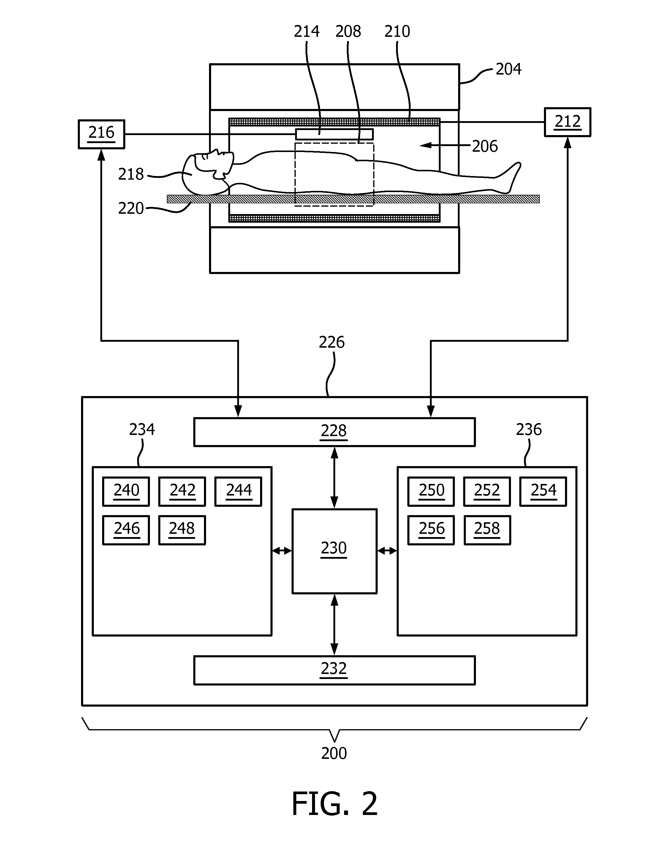
[0072]Like numbered elements in these figures are either equivalent elements or perform the same function. Elements which have been discussed previously will not necessarily be discussed in later figures if the function is equivalent.

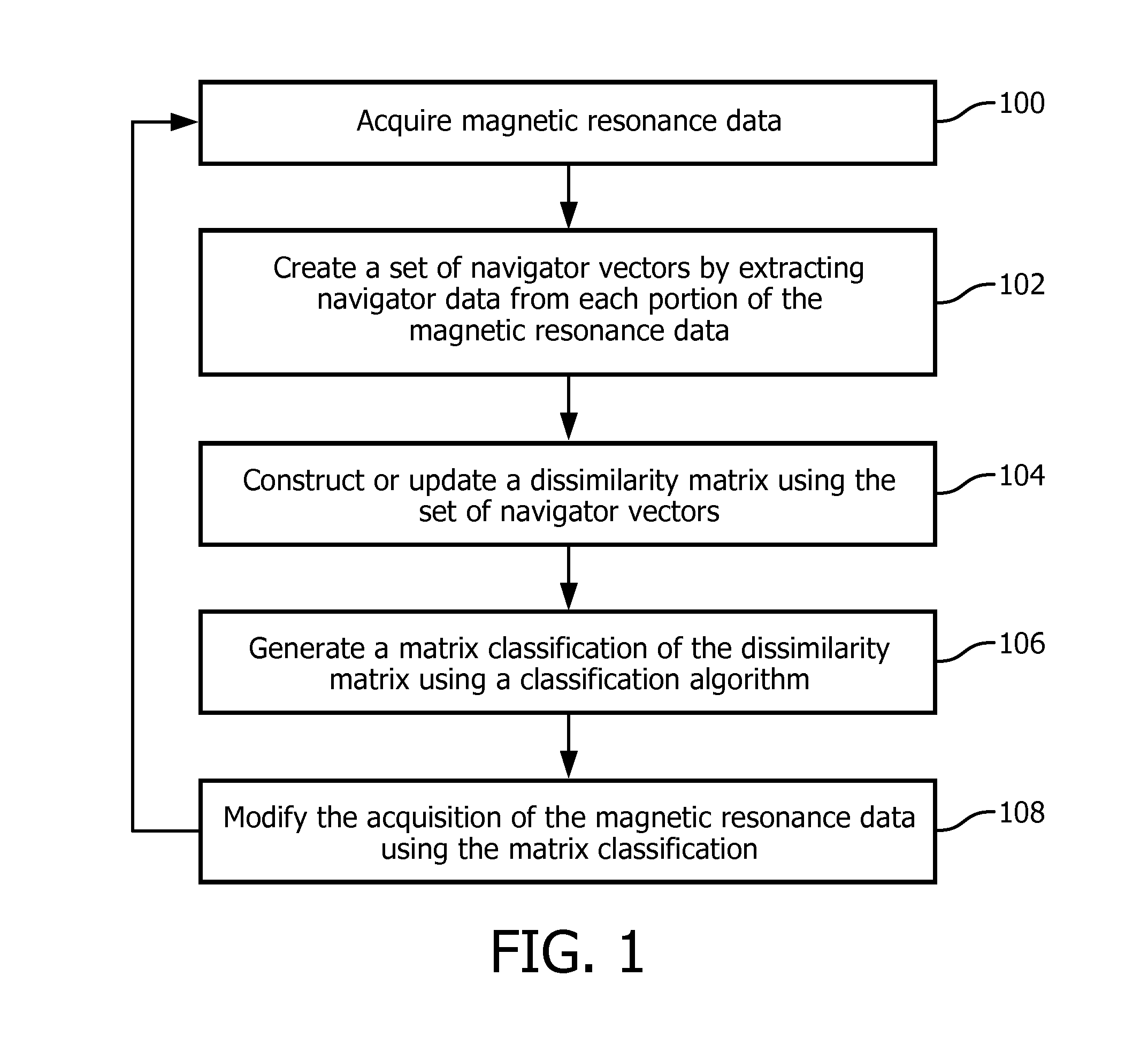
[0073]FIG. 1 shows a flow diagram which illustrates a method according to an embodiment of the invention. First in step 100 magnetic resonance data is acquired. The magnetic resonance system acquires a portion of the magnetic resonance data. Each portion of the magnetic resonance data comprises navigator data. Next in step 102 a set of navigator vectors are created by extracting navigator data from each portion of the magnetic resonance data. Next in step 104 a dissimilarity matrix is calculated using a metric between each of the set of navigator vectors. As this is an iterative process the dissimilarity matrix may simply be updated from a previous version by adding newly acquired navigator vectors and calculating the dissimilarity between the existing ...


PUM


Abstract

The invention provides for a magnetic resonance imaging system (200, 300) for acquiring magnetic resonance data (242, 244). A processor (230) for controlling the magnetic resonance imaging system executes instructions (250, 252, 254, 256, 258) which cause the processor to repeatedly: control (100) the magnetic resonance imaging system to acquire a portion of the magnetic resonance data, wherein each portion of the magnetic resonance data comprises navigator data (244); create (102) a set of navigator vectors by extracting the navigator data from each portion of the magnetic resonance data; construct (104) a dissimilarity matrix (246, 400, 700, 800, 900, 1000, 1100, 1400, 1500) by calculating a metric between each of the set of navigator vectors; generate (106) a matrix classification (248) of the dissimilarity matrix using a classification algorithm; and control (108) the magnetic resonance imaging system to modify acquisition of the magnetic resonance data using the matrix classification.

Description

TECHNICAL FIELD[0001]The invention relates to magnetic resonance imaging, in particular to the modification of the acquisition of magnetic resonance imaging using a dissimilarity matrix classification.BACKGROUND OF THE INVENTION[0002]Patient motion during magnetic resonance imaging (MRI) data acquisition can lead to image artifacts which compromise the diagnostic quality of the resulting images. This is an important problem and has lead to a large number of methods which aim at reducing the impact of patient motion. Despite these past efforts, patient motion is still an important problem today; partly because increased SNR and fast scan methods of modern magnetic resonance (MR) scanners allow imaging at higher spatial resolution which makes the experiment more sensitive to motion, partly because the proposed methods are impractical in routine clinical use. This can be the case either because they require sensors which are too complicated and / or time consuming to connect, or because ...

Claims


Application Information

Patent Timeline
Patent Type & Authority Applications(United States)
IPC IPC(8): G01R33/565
CPCG01R33/56509
Inventor NIELSEN, TIMBORNERT, PETER
Owner KONINKLJIJKE PHILIPS NV
Learn More